Introduction to PCB Drill Speed Control
Drilling is a critical operation in the manufacturing of printed circuit boards (PCBs). The speed at which the drill bit rotates and advances into the PCB material has a significant impact on hole quality, tool life, and overall productivity. Therefore, precise control over the drill speed is essential for achieving optimal results in PCB Drilling.
Key Factors Influencing PCB Drill Speed
Several factors influence the appropriate speed for drilling PCBs:
- Material properties
- PCB Substrate (e.g., FR-4, ceramic, polyimide)
- Copper thickness
- Number of layers
- Drill bit characteristics
- Diameter
- Material (e.g., carbide, diamond-coated)
- Geometry (e.g., split point, multi-flute)
- Hole specifications
- Diameter
- Aspect ratio (depth to diameter)
- Tolerance requirements
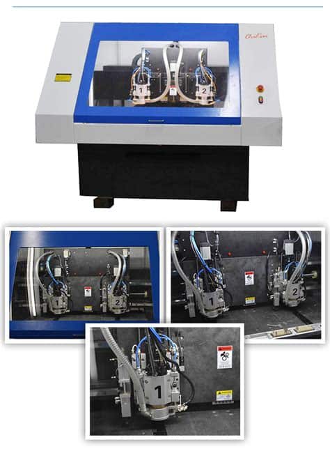
- Machine capabilities
- Spindle speed range
- Feed rate range
- Cooling and lubrication system
Determining Optimal PCB Drill Speed
To determine the optimal speed for drilling PCBs, engineers and machine operators need to consider the interplay of various factors and find a balance that yields the desired hole quality while maximizing productivity and tool life.
Material Properties and Drill Speed
The properties of the PCB material have a direct impact on the appropriate drill speed. Harder materials, such as ceramics and polyimides, require lower speeds to prevent excessive wear on the drill bit and maintain hole quality. Softer materials, like standard FR-4, can typically be drilled at higher speeds.
The thickness of the copper layers also influences drill speed. Thicker copper layers require lower speeds to prevent drill bit breakage and ensure clean hole formation. The number of layers in the PCB stack-up affects the total drilling depth and may necessitate speed adjustments to maintain consistent hole quality throughout the stack.
Drill Bit Characteristics and Speed
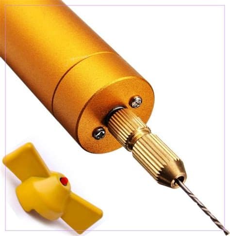
The characteristics of the drill bit, including its diameter, material, and geometry, play a crucial role in determining the appropriate speed for PCB drilling.
Smaller diameter drill bits generally require higher rotational speeds to maintain a suitable cutting velocity at the tool-material interface. However, excessive speeds can lead to premature wear and breakage, particularly for very small drill bits.
The material of the drill bit also influences the speed range. Carbide drill bits are commonly used for PCB drilling and can withstand higher speeds than high-speed steel (HSS) bits. Diamond-coated drill bits offer superior wear resistance and can operate at even higher speeds, but they are more expensive.
The geometry of the drill bit, such as the point angle and flute design, affects the cutting action and chip evacuation. Split point drill bits, for example, can operate at higher speeds than conventional point drill bits due to their improved self-centering and chip-breaking capabilities.
Hole Specifications and Drill Speed
The hole specifications, including diameter, aspect ratio, and tolerance requirements, dictate the appropriate speed range for PCB drilling.
Smaller hole diameters require higher speeds to maintain a suitable cutting velocity, but the maximum speed is limited by the drill bit’s size and the machine’s capabilities. High aspect ratio holes (depth to diameter ratio greater than 10:1) may require reduced speeds to prevent drill bit wandering and ensure straight, high-quality holes.
Tighter tolerance requirements for hole diameter and position accuracy may necessitate lower drilling speeds to minimize vibration and deflection of the drill bit.
Machine Capabilities and Drill Speed
The capabilities of the PCB drilling machine, including its spindle speed range, feed rate range, and cooling and lubrication system, set the boundaries for the achievable drill speeds.
High-performance drilling machines offer a wide range of spindle speeds, allowing optimization for various drill bit sizes and materials. The machine’s maximum feed rate determines the limit for the axial advancement of the drill bit into the PCB material.
Effective cooling and lubrication are essential for High-speed PCB drilling to remove heat from the cutting zone, reduce friction, and extend drill bit life. The machine’s coolant delivery system and the properties of the cutting fluid (e.g., viscosity, heat capacity) influence the maximum sustainable drill speed.

Drill Speed Optimization Techniques
Several techniques can be employed to optimize drill speed and achieve the best balance of hole quality, productivity, and tool life in PCB drilling.
Speed and Feed Rate Adjustment
One of the primary methods for optimizing drill speed is to adjust the spindle speed and feed rate based on the specific requirements of the job. This involves selecting the appropriate speed range for the given drill bit size, material, and PCB properties, and then fine-tuning the speed within that range to achieve the desired results.
Feed rate, which determines the axial advancement of the drill bit into the PCB material, is typically adjusted in conjunction with the spindle speed. Higher feed rates can improve productivity but may require lower spindle speeds to maintain hole quality and prevent drill bit breakage.
Example speed and feed rate combinations for different drill bit sizes in FR-4 PCB material:
| Drill Bit Diameter (mm) | Spindle Speed (RPM) | Feed Rate (mm/min) |
|---|---|---|
| 0.2 | 80,000 – 120,000 | 200 – 400 |
| 0.5 | 50,000 – 80,000 | 400 – 800 |
| 1.0 | 30,000 – 50,000 | 800 – 1,500 |
| 2.0 | 15,000 – 30,000 | 1,500 – 3,000 |
Peck Drilling Cycle
Peck drilling is a technique used to improve hole quality and evacuate chips when drilling deep holes or working with challenging materials. In a peck drilling cycle, the drill bit advances into the material by a specified depth (peck depth), retracts to clear the chips, and then advances again, repeating this process until the full hole depth is reached.
Peck drilling allows for better chip evacuation, reducing heat buildup and preventing drill bit breakage. It also helps to minimize smearing and burring of the hole walls, particularly in multi-layer PCBs with alternating layers of copper and dielectric material.
The peck depth and retract distance are programmed into the drilling machine’s control system and can be optimized based on the hole depth, material properties, and drill bit characteristics.
Drill Bit Selection and Maintenance
Proper selection and maintenance of drill bits are crucial for achieving optimal speed and hole quality in PCB drilling. The drill bit material, geometry, and coating should be chosen based on the specific requirements of the job, considering factors such as the PCB material, hole size, and aspect ratio.
Regularly inspecting and replacing worn or damaged drill bits is essential for maintaining consistent hole quality and preventing production delays due to drill bit failure. Implementing a drill bit management system, which tracks the usage and performance of individual drill bits, can help optimize drill bit life and minimize unplanned downtime.
Cooling and Lubrication Optimization
Effective cooling and lubrication are critical for high-speed PCB drilling, as they help to dissipate heat, reduce friction, and extend drill bit life. Optimizing the cooling and lubrication system involves selecting the appropriate cutting fluid, adjusting the flow rate and pressure, and ensuring proper delivery of the fluid to the cutting zone.
Water-soluble cutting fluids are commonly used for PCB drilling, as they provide good cooling and lubrication properties while being environmentally friendly and easy to maintain. The concentration of the cutting fluid should be regularly monitored and adjusted to ensure optimal performance.
Minimum quantity lubrication (MQL) systems, which deliver a fine mist of cutting fluid directly to the cutting zone, can be used to reduce fluid consumption and improve hole quality in high-speed PCB drilling applications.

Monitoring and Control Systems for PCB Drill Speed
To ensure consistent hole quality and optimize the drilling process, modern PCB drilling machines incorporate advanced monitoring and control systems for drill speed and other critical parameters.
Spindle Speed and Feed Rate Monitoring
Spindle speed and feed rate are continuously monitored during the drilling process using sensors and encoders built into the machine’s spindle and feed axis. This real-time data is used to verify that the actual speed and feed rate match the programmed values and to detect any deviations that could indicate issues with the drilling process.
Closed-loop control systems automatically adjust the spindle speed and feed rate based on the monitored data to maintain the desired values and compensate for variations in material properties or tool wear.
Drill Bit Wear and Breakage Detection
Monitoring drill bit wear and detecting breakage is essential for maintaining hole quality and preventing damage to the PCB or the machine. Several methods can be used to monitor drill bit condition:
-
Spindle torque monitoring: Changes in spindle torque can indicate drill bit wear or breakage, as a worn or damaged drill bit requires more power to cut through the material.
-
Acoustic emission monitoring: Sensors can detect changes in the acoustic emissions generated during drilling, which can indicate drill bit wear or breakage.
-
Vision-based monitoring: Cameras and image processing algorithms can be used to visually inspect the drill bit condition and detect wear or damage.
When a worn or broken drill bit is detected, the machine can automatically stop the drilling process and alert the operator to replace the drill bit, minimizing the risk of producing non-conforming holes or damaging the PCB.
Adaptive Speed Control
Adaptive speed control systems use real-time data from the monitoring systems to dynamically adjust the drill speed based on the actual conditions of the drilling process. These systems can compensate for variations in material properties, drill bit wear, and other factors that impact hole quality and productivity.
For example, an adaptive speed control system may reduce the drill speed when detecting increased spindle torque, indicating drill bit wear or a harder material zone. Conversely, the system may increase the speed when conditions allow for faster drilling without compromising hole quality.
Adaptive speed control systems help to optimize the drilling process, extending drill bit life, improving hole quality, and reducing cycle times.

Frequently Asked Questions (FAQ)
1. What is the most important factor in determining the appropriate speed for PCB drilling?
The most important factor in determining the appropriate speed for PCB drilling is the drill bit diameter. Smaller drill bits require higher speeds to maintain a suitable cutting velocity, while larger drill bits can be run at lower speeds. However, other factors such as material properties, hole specifications, and machine capabilities also play a crucial role in optimizing drill speed.
2. How does the material of the PCB affect the drill speed?
The properties of the PCB material, such as hardness and thermal conductivity, have a direct impact on the appropriate drill speed. Harder materials, like ceramics and polyimides, require lower speeds to prevent excessive wear on the drill bit and maintain hole quality. Softer materials, such as standard FR-4, can typically be drilled at higher speeds. The thickness of the copper layers and the number of layers in the PCB stack-up also influence the drill speed, as they affect the total drilling depth and the heat generated during the process.
3. What is peck drilling, and how does it improve hole quality?
Peck drilling is a technique used to improve hole quality and evacuate chips when drilling deep holes or working with challenging materials. In a peck drilling cycle, the drill bit advances into the material by a specified depth (peck depth), retracts to clear the chips, and then advances again, repeating this process until the full hole depth is reached. Peck drilling allows for better chip evacuation, reducing heat buildup and preventing drill bit breakage. It also helps to minimize smearing and burring of the hole walls, particularly in multi-layer PCBs with alternating layers of copper and dielectric material.
4. How can drill bit wear and breakage be detected during the PCB drilling process?
Several methods can be used to monitor drill bit wear and detect breakage during the PCB drilling process:
-
Spindle torque monitoring: Changes in spindle torque can indicate drill bit wear or breakage, as a worn or damaged drill bit requires more power to cut through the material.
-
Acoustic emission monitoring: Sensors can detect changes in the acoustic emissions generated during drilling, which can indicate drill bit wear or breakage.
-
Vision-based monitoring: Cameras and image processing algorithms can be used to visually inspect the drill bit condition and detect wear or damage.
When a worn or broken drill bit is detected, the machine can automatically stop the drilling process and alert the operator to replace the drill bit, minimizing the risk of producing non-conforming holes or damaging the PCB.
5. What are the benefits of using an adaptive speed control system in PCB drilling?
Adaptive speed control systems use real-time data from monitoring systems to dynamically adjust the drill speed based on the actual conditions of the drilling process. These systems can compensate for variations in material properties, drill bit wear, and other factors that impact hole quality and productivity. The benefits of using an adaptive speed control system in PCB drilling include:
-
Extended drill bit life: By adjusting the speed based on the actual conditions, adaptive speed control systems can prevent excessive wear on the drill bit, extending its usable life.
-
Improved hole quality: Adaptive speed control helps maintain consistent hole quality by compensating for variations in material properties and drill bit wear.
-
Reduced cycle times: By optimizing the drill speed in real-time, adaptive speed control systems can minimize the time required to drill each hole, improving overall productivity.
-
Minimized risk of drill bit breakage: By detecting and responding to changes in drilling conditions, adaptive speed control systems can prevent drill bit breakage, reducing unplanned downtime and scrap.
Conclusion
Precise control over drill speed is essential for achieving optimal results in PCB drilling, as it directly impacts hole quality, tool life, and productivity. Determining the appropriate speed involves considering various factors, such as material properties, drill bit characteristics, hole specifications, and machine capabilities.
Optimizing drill speed requires a combination of techniques, including speed and feed rate adjustment, peck drilling, proper drill bit selection and maintenance, and cooling and lubrication optimization. Advanced monitoring and control systems, such as spindle speed and feed rate monitoring, drill bit wear and breakage detection, and adaptive speed control, help ensure consistent hole quality and optimize the drilling process.
By understanding the factors influencing PCB drill speed and implementing the appropriate optimization techniques and monitoring systems, manufacturers can improve hole quality, extend drill bit life, and increase productivity in their PCB drilling operations.

No responses yet