
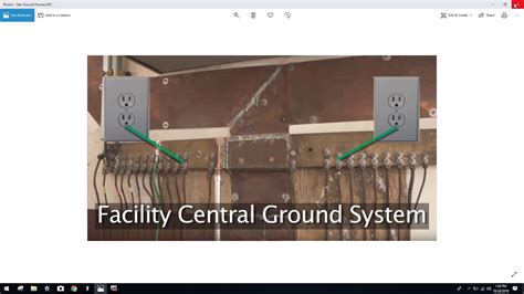
What is Star-Grounding?
Star-grounding is a technique used in electrical and electronic systems to minimize noise and interference by creating a single, central grounding point for all components. This method is particularly useful when dealing with mixed-signal circuits that include both analog and digital components, as it helps to prevent ground loops and reduce the impact of digital switching noise on sensitive analog signals.
In a star-grounding configuration, each component or subsystem is connected to a common ground point, typically referred to as the “star point.” This central grounding point is usually located near the power supply or at a point where the analog and digital grounds are separated.
Advantages of Star-Grounding
-
Reduces ground loops: By providing a single, low-impedance path to ground, star-grounding minimizes the formation of ground loops, which can cause unwanted noise and interference.
-
Improves signal integrity: With a properly implemented star-grounding system, sensitive analog signals are less likely to be affected by digital switching noise, resulting in improved signal quality and accuracy.
-
Simplifies troubleshooting: When issues arise, a star-grounding configuration makes it easier to identify and isolate the source of the problem, as each component has a dedicated ground connection.
Implementing Star-Grounding in Mixed-Signal Circuits
When designing a mixed-signal circuit that incorporates both analog and digital components, it is essential to consider the grounding strategy early in the design process. Proper star-grounding can help ensure optimal performance and reliability.
Separating Analog and Digital Grounds
One of the key aspects of implementing star-grounding in a mixed-signal circuit is separating the analog and digital grounds. This is done to prevent digital switching noise from coupling into sensitive analog signals.
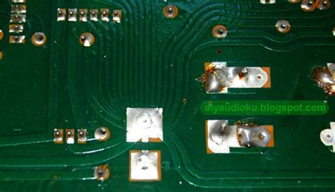
To achieve this separation, create two distinct ground planes or traces on the PCB: one for analog ground (AGND) and another for digital ground (DGND). These planes should be connected at a single point, typically near the power supply or at the star point.
Placing the Star Point
The location of the star point is crucial for effective grounding. Consider the following guidelines when placing the star point:
-
Proximity to the power supply: Placing the star point near the power supply helps to minimize the impedance between the supply and the grounding system, reducing noise and voltage drops.
-
Centralized location: Ideally, the star point should be located at a central position relative to the components it serves. This helps to minimize the trace lengths and maintain a low-impedance path to ground.
-
Accessibility: Ensure that the star point is easily accessible for testing and debugging purposes.
Connecting Components to the Star Point
When connecting components to the star point, use the following best practices:
-
Short, wide traces: Use short, wide traces to connect each component to the star point. This minimizes the Trace Impedance and reduces the potential for noise coupling.
-
Separate ground returns: Provide separate ground return paths for analog and digital components. This helps to prevent digital switching currents from flowing through sensitive analog ground traces.
-
Filtered connections: If necessary, use Ferrite beads or low-pass filters to isolate noisy digital components from the star point and prevent high-frequency noise from propagating through the grounding system.
Practical Examples of Star-Grounding
Example 1: Audio Amplifier with Digital Control
Consider an audio amplifier that includes a digital control circuit for volume and tone adjustments. In this case, star-grounding can be used to minimize the impact of digital switching noise on the analog audio signal.
- Separate the analog and digital ground planes on the PCB.
- Place the star point near the power supply, close to the audio amplifier’s ground connection.
- Connect the analog ground plane to the star point using a short, wide trace.
- Connect the digital ground plane to the star point using a separate trace, possibly with a ferrite bead or low-pass filter to isolate high-frequency noise.
- Ensure that the digital control circuit’s ground return path is connected to the digital ground plane, while the audio amplifier’s ground is connected to the analog ground plane.
Example 2: Data Acquisition System with Analog Sensors
In a data acquisition system that uses analog sensors and a digital microcontroller, star-grounding can help ensure accurate sensor readings by minimizing noise coupling between the digital and analog components.
- Create separate analog and digital ground planes on the PCB.
- Position the star point near the power supply, close to the microcontroller’s ground pin.
- Connect the analog ground plane to the star point using a short, wide trace.
- Connect the digital ground plane to the star point using a separate trace.
- Ensure that the analog sensors’ ground connections are routed to the analog ground plane, while the microcontroller’s ground pin is connected to the digital ground plane.
- Use ferrite beads or low-pass filters on the connections between the microcontroller and the analog sensors to minimize high-frequency noise coupling.

Alternatives to Star-Grounding
While star-grounding is a widely used and effective technique for minimizing noise and interference in mixed-signal circuits, there are alternative grounding strategies that may be suitable in certain situations.
Multi-Point Grounding
In a multi-point grounding system, components are connected to ground at multiple points rather than a single star point. This approach can be useful in large, complex systems where a single star point may not be practical or effective.
However, multi-point grounding requires careful design to avoid ground loops and ensure that the ground connections are properly balanced. Simulations and thorough testing are essential to validate the grounding strategy.
Hybrid Grounding
Hybrid grounding combines elements of star-grounding and multi-point grounding. In this approach, smaller subsystems or components may have their own local star points, which are then connected to a main star point or ground plane.
This technique can be effective in systems with distinct functional blocks or modules, as it allows for some degree of isolation between the subsystems while still maintaining a low-impedance path to ground.
Frequently Asked Questions (FAQ)
-
Q: When is star-grounding most commonly used?
A: Star-grounding is most commonly used in mixed-signal circuits that include both analog and digital components, as it helps to minimize noise coupling and improve signal integrity. -
Q: What are the main benefits of using star-grounding?
A: The main benefits of using star-grounding include reducing ground loops, improving signal integrity, and simplifying troubleshooting. -
Q: How do I separate analog and digital grounds in a star-grounding configuration?
A: To separate analog and digital grounds, create two distinct ground planes or traces on the PCB: one for analog ground (AGND) and another for digital ground (DGND). These planes should be connected at a single point, typically near the power supply or at the star point. -
Q: What should I consider when placing the star point in a star-grounding system?
A: When placing the star point, consider proximity to the power supply, a centralized location relative to the components it serves, and accessibility for testing and debugging purposes. -
Q: Are there any alternatives to star-grounding?
A: Yes, alternatives to star-grounding include multi-point grounding and hybrid grounding. However, these strategies may require more careful design and validation to ensure proper performance.
Conclusion
Star-grounding is a powerful technique for minimizing noise and interference in mixed-signal circuits that incorporate both analog and digital components. By providing a single, low-impedance path to ground and separating analog and digital ground planes, star-grounding can help to reduce ground loops, improve signal integrity, and simplify troubleshooting.
When implementing star-grounding, it is essential to consider the placement of the star point, the separation of analog and digital grounds, and the proper connection of components to the star point. By following best practices and carefully designing the grounding system, engineers can ensure optimal performance and reliability in their mixed-signal designs.
While alternative grounding strategies, such as multi-point grounding and hybrid grounding, may be suitable in certain situations, star-grounding remains a widely used and effective approach for many applications. As with any design decision, thorough simulations and testing are crucial to validate the chosen grounding strategy and ensure that the system meets its performance requirements.
No responses yet