What is a Differential Stripline?
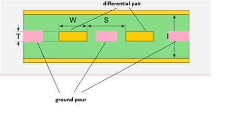
A differential stripline is a type of transmission line commonly used in high-speed digital circuits for differential signaling. It consists of two parallel traces routed between two ground planes. The geometry and spacing of the traces determines the characteristic impedance of the differential pair.
Differential signaling has several advantages over single-ended signaling:
– Improved noise immunity
– Reduced electromagnetic emissions
– Allows higher data rates
To achieve these benefits, it’s critical that the differential stripline is designed to have the desired characteristic impedance, typically 100 ohms. This is where a Stripline Impedance calculator becomes a valuable tool.
How a Stripline Impedance Calculator Works
A stripline impedance calculator uses formulas based on the physical and electrical properties of the stripline to determine the characteristic impedance. The key parameters are:
- Dielectric constant (Dk) of the insulating material
- Height (H) between the ground planes
- Thickness (T) of the traces
- Width (W) of the traces
- Spacing (S) between the traces
The calculator takes these inputs and computes the odd-mode and even-mode impedances, which together determine the differential impedance. The odd-mode impedance (Zodd) assumes the traces have equal and opposite currents, while the even-mode impedance (Zeven) assumes equal currents flowing in the same direction.
The differential impedance (Zdiff) is then given by:
Zdiff = 2 * sqrt(Zodd * Zeven)
Typical target values are:
– Zodd: 60 ohms
– Zeven: 40 ohms
– Zdiff: 100 ohms
Achieving these targets requires carefully adjusting the trace width, spacing, and dielectric height. A good Stripline Calculator makes this optimization process much easier.
Online Stripline Impedance Calculators
Many free online tools are available to calculate differential stripline impedances. These provide a convenient way to explore different stackup and trace geometries. Some of the most popular online calculators include:
| Calculator | URL |
|---|---|
| Multi-tek | https://www.multi-circuit-boards.eu/en/pcb-design-aid/differential-stripline-impedance.html |
| EEWeb | https://www.eeweb.com/tools/differential-stripline-impedance |
| All About Circuits | https://www.allaboutcircuits.com/tools/differential-stripline-impedance-calculator/ |
While very useful for initial what-if analysis, keep in mind that online calculators make some simplifying assumptions that may not match your manufacturing process. Always verify the impedance with your fabricator before finalizing the design.

Stripline Calculator Formulas
For those who want to understand the underlying math, here are the formulas used to calculate differential stripline impedances:
Odd-Mode Impedance
Zodd = (80/sqrt(eff_Er)) * log(1.9(2H-T)/(0.8*W+T))
Even-Mode Impedance
Zeven = (80/sqrt(eff_Er)) * log(4H/(0.67pi*W))
Where:
– eff_Er = effective dielectric constant
– H = height between ground planes (mils)
– T = trace thickness (mils)
– W = trace width (mils)
The effective dielectric constant (eff_Er) accounts for the fields propagating through both the substrate material and air. It depends on the substrate’s dielectric constant (Er) and the ratio of trace width to dielectric height (W/H):
eff_Er =0.5 [Er + 1 + (Er-1) * (1/sqrt(1 + 12 H/W))]
Designing to a Target Impedance
The goal is usually to design the stripline to have a specific differential impedance, such as 100 ohms. This is done by adjusting the trace width (W) and spacing (S) relative to the height (H) set by the PCB stackup.
A typical approach is:
1. Choose a standard stackup height (H)
2. Set the trace width and spacing to estimated initial values
3. Use the stripline calculator to determine Zodd and Zeven
4. Adjust W and S proportionally to move Zdiff closer to the target
5. Repeat steps 3-4 until the target impedance is achieved
For example, let’s say we want to design a 100 ohm differential stripline in a 4-layer PCB stackup with 8 mil core heights (H=8). The dielectric is FR-4 with Er=4.2 and the copper weight is 1 oz (T=1.4).
We might start with 5 mil traces spaced 5 mils apart (W=S=5). Plugging into the calculator shows this gives Zodd=59 and Zeven=36, resulting in Zdiff=94 ohms. To increase the impedance, we can make the traces narrower.
Updating the calculation with W=S=4 gives Zodd=65 and Zeven=41 for a Zdiff of 103 ohms. This is close enough to 100 for most designs. If more precision is needed, the spacing can be increased slightly relative to the width to fine tune the final result.
Dealing with Manufacturing Tolerances
PCB manufacturing has inherent variations that affect impedance. Traces may end up slightly wider or narrower than designed due to etching tolerances. The substrate Er may also vary from nominal. These variations can cause the actual impedance to deviate from the target.
To account for this, it’s best to design to the middle of the impedance tolerance range. For example, if the spec is 100 ohms +/- 10%, design for 105 ohms. This gives margin for manufacturing variations.
It’s also important to specify controlled impedance when ordering the PCB. This tells the fabricator to adjust the trace widths and spacings as needed to deliver the required impedance. There is usually an added cost for controlled impedance, but it is essential for high-speed designs.
Measuring Stripline Impedance
Calculated impedances should always be verified by measurement. This gives the true impedance, accounting for any variations in the materials and manufacturing process.
The gold standard for measuring stripline impedance is a Time Domain Reflectometer (TDR). A TDR sends a fast risetime pulse down the line and measures the reflections. The shape of the reflections indicates the impedance along the line.
For differential striplines, the TDR needs to support differential TDR with dual heads. The differential impedance is found by mathematically combining the single-ended impedances measured from each line to its local ground (technically Zeven and Zodd).
If a differential TDR is not available, an acceptable approximation is to use a single-ended TDR to measure each trace to ground, then multiply that impedance by two. This relies on the grounds being well-balanced and is not as accurate as a true differential measurement.
When making TDR measurements, it’s important to use high quality test fixturing. The fixture and probes should be rated to at least the risetime of the TDR. Poor fixturing adds reflections that corrupt the impedance measurement.
FAQ
What is the typical impedance of a differential stripline?
100 ohms is the most common target. Some high-speed memory designs use lower impedances in the 80-85 ohm range. RF applications may require higher impedances of 110-120 ohms.
How do you calculate differential stripline impedance?
Differential stripline impedance is calculated from the odd-mode and even-mode impedances. These depend on the trace geometry, spacing, and dielectric properties. The calculations are complex, so impedance calculators are typically used. See the formulas section in this article for details.
What happens if the differential impedance is wrong?
The main risk of incorrect impedance is reflections. If the impedance has discontinuities, some of the signal energy will reflect back to the source instead of being delivered to the load. This degrades signal integrity and may cause bit errors at high data rates. Mismatched impedance can also increase electromagnetic emissions.
How much does PCB impedance control cost?
Specifying controlled impedance usually adds 10-30% to the PCB cost. The actual upcharge depends on the number of impedances being controlled, the tolerances required, and the volume ordered. Fabricators may waive the impedance adder for high volumes.
What if my PCB vendor doesn’t control impedance?
Avoid using vendors that do not offer controlled impedance for high-speed designs. The risk of signal integrity problems is too high without impedance control. If you are forced to use a low-end vendor, at least have them cross-section the PCB to confirm the geometries are close to the design targets.
No responses yet