Introduction to Stripline Impedance
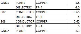
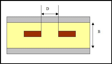
Stripline is a type of transmission line that is widely used in high-frequency electronic circuits, such as microwave and radio frequency (RF) applications. It consists of a flat conductor strip sandwiched between two parallel ground planes, with a dielectric material filling the space between them. The characteristic impedance of a stripline is an essential parameter that determines its electrical behavior and is crucial for designing impedance-matched circuits to minimize signal reflections and power loss.
In this article, we will explore the concept of stripline impedance, its importance in electronic design, and various methods to calculate it using formulas and online calculators. We will also discuss the factors that influence stripline impedance and provide practical tips for designing striplines with specific impedance values.
What is Stripline Impedance?
Stripline impedance, also known as characteristic impedance, is the ratio of the voltage to the current traveling along a stripline transmission line. It is a complex quantity that depends on the geometry of the stripline, the properties of the dielectric material, and the frequency of the signal. The characteristic impedance is typically expressed in ohms (Ω) and is denoted by the symbol Z₀.
In an ideal stripline, the characteristic impedance is purely real and remains constant along the length of the line. However, in practice, striplines have finite conductivity and dielectric losses, which introduce a small imaginary component to the impedance. This imaginary part represents the power dissipation in the line and is usually negligible compared to the real part.
Importance of Stripline Impedance
Stripline impedance plays a crucial role in the design of high-frequency electronic circuits for several reasons:
-
Impedance Matching: To minimize signal reflections and ensure maximum power transfer, the impedance of the stripline must match the impedance of the source and load connected to it. Any mismatch in impedance will cause a portion of the signal to be reflected back, leading to signal distortion and power loss.
-
Signal Integrity: Maintaining a consistent stripline impedance throughout the circuit helps to preserve the integrity of the transmitted signal. Abrupt changes in impedance can cause reflections, ringing, and other signal degradation effects that can compromise the performance of the system.
-
Frequency Response: The stripline impedance affects the frequency response of the transmission line. A well-designed stripline with a constant impedance will have a flat frequency response over a wide bandwidth, enabling the transmission of high-speed signals without distortion.
-
Power Handling: The impedance of the stripline determines its power handling capability. A higher impedance stripline can withstand higher voltages but carries less current, while a lower impedance stripline can carry more current but is limited in voltage.
Factors Affecting Stripline Impedance
The characteristic impedance of a stripline depends on several factors related to its geometry and material properties. The main factors are:
-
Width of the Conductor Strip: The width of the center conductor strip (W) is one of the most significant factors affecting stripline impedance. Increasing the width lowers the impedance, while decreasing the width raises the impedance.
-
Thickness of the Dielectric: The thickness of the dielectric material (H) between the conductor strip and the ground planes also influences the impedance. A thicker dielectric results in a higher impedance, while a thinner dielectric leads to a lower impedance.
-
Dielectric Constant: The dielectric constant (εᵣ) of the insulating material between the conductor and ground planes affects the impedance. A higher dielectric constant reduces the impedance, while a lower dielectric constant increases it.
-
Thickness of the Conductor: The thickness of the conductor strip (T) has a minor effect on the impedance. In general, a thicker conductor results in a slightly lower impedance, but this effect is less significant compared to the other factors.
-
Frequency: The characteristic impedance of a stripline is frequency-dependent due to the skin effect and dielectric dispersion. However, for most practical applications, the impedance can be considered constant over a wide frequency range.

Stripline Impedance Formulas
There are several formulas available to calculate the characteristic impedance of a symmetric stripline based on its geometry and material properties. These formulas provide a good approximation of the impedance and are widely used in the design of stripline circuits. Here are two commonly used formulas:
1. Hammerstad and Jensen Formula
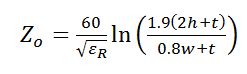
The Hammerstad and Jensen formula is a widely used empirical formula for calculating the characteristic impedance of a symmetric stripline. It is given by:
Z₀ = (60 / √εᵣ) * ln(1.9 * (H / W) + 2)
Where:
– Z₀ is the characteristic impedance in ohms (Ω)
– εᵣ is the relative dielectric constant of the insulating material
– H is the thickness of the dielectric between the conductor strip and ground planes in meters (m)
– W is the width of the conductor strip in meters (m)
This formula is accurate for a wide range of stripline geometries and is valid for the following conditions:
– 0.1 ≤ W/H ≤ 10
– 1 ≤ εᵣ ≤ 16
2. Wheeler Formula
The Wheeler formula is another popular formula for calculating the characteristic impedance of a symmetric stripline. It is based on conformal mapping techniques and is given by:
Z₀ = (377 / (4 * √εᵣ)) * (H / W) * (1 - (H / (2 * W)) * (1 - ln(4 * W / H)))
Where:
– Z₀ is the characteristic impedance in ohms (Ω)
– εᵣ is the relative dielectric constant of the insulating material
– H is the thickness of the dielectric between the conductor strip and ground planes in meters (m)
– W is the width of the conductor strip in meters (m)
The Wheeler formula is accurate for a wide range of stripline geometries and is valid for the following conditions:
– 0.1 ≤ W/H ≤ 10
– 1 ≤ εᵣ ≤ 16
Online Stripline Impedance Calculators
In addition to the formulas, there are several online calculators available that can quickly and easily determine the characteristic impedance of a stripline based on its geometry and material properties. These calculators are convenient tools for designers and engineers, as they eliminate the need for manual calculations and provide accurate results. Some popular online stripline impedance calculators include:
- Microstrip Impedance Calculator by EverythingRF
- Stripline Impedance Calculator by All About Circuits
- Symmetric Stripline Impedance Calculator by Microwaves101
To use these calculators, you typically need to input the following parameters:
– Width of the conductor strip (W)
– Thickness of the dielectric (H)
– Relative dielectric constant of the insulating material (εᵣ)
– Thickness of the conductor strip (T) (optional)
The calculator will then provide the characteristic impedance of the stripline based on the entered values. Some calculators also offer additional features, such as the ability to calculate the width of the conductor strip for a given impedance and dielectric thickness.
Designing Striplines with Specific Impedance
When designing stripline circuits, it is often necessary to achieve a specific characteristic impedance to ensure proper impedance matching and signal integrity. Here are some practical tips for designing striplines with a desired impedance:
-
Choose the Right Dielectric Material: Select a dielectric material with a suitable dielectric constant (εᵣ) for your application. Common materials used in stripline circuits include FR-4, Rogers RO4003, and Teflon. Keep in mind that the dielectric constant affects the impedance, so choose a material that allows you to achieve the desired impedance with reasonable dimensions.
-
Determine the Dielectric Thickness: The thickness of the dielectric (H) is usually determined by the available materials and manufacturing constraints. A thicker dielectric will result in a higher impedance, while a thinner dielectric will lower the impedance. Consider the maximum and minimum achievable dielectric thicknesses based on your fabrication process.
-
Calculate the Conductor Width: Use one of the stripline impedance formulas or an online calculator to determine the required width of the conductor strip (W) for the desired impedance. Keep in mind that the width should be within the valid range of the formula or calculator you are using.
-
Adjust the Design: If the calculated conductor width is not practical or feasible due to manufacturing limitations, you may need to adjust other parameters, such as the dielectric thickness or material, to achieve the desired impedance. Use the formulas or calculators iteratively to find a suitable combination of parameters that meets your requirements.
-
Consider Conductor Thickness: While the thickness of the conductor strip (T) has a minor effect on the impedance, it is still important to choose an appropriate thickness based on the current-carrying requirements and manufacturing capabilities. A thicker conductor will have lower losses and better power handling capacity but may be more challenging to fabricate.
-
Verify the Design: Once you have designed the stripline with the desired impedance, it is essential to verify the design using electromagnetic simulation tools, such as Ansys HFSS, CST Studio Suite, or Keysight ADS. These tools can accurately model the stripline and take into account factors such as conductor losses, dielectric losses, and dispersion, which are not considered in the simplified formulas.
-
Prototype and Test: After verifying the design through simulations, create a prototype of the stripline circuit and test it experimentally to validate its performance. Measure the impedance using a vector network analyzer (VNA) or time-domain reflectometer (TDR) to ensure that it matches the designed value. Make any necessary adjustments based on the measurement results.
By following these tips and using the appropriate formulas and calculators, you can design striplines with specific impedance values to meet the requirements of your high-frequency electronic circuits.
Conclusion
Stripline impedance is a critical parameter in the design of high-frequency electronic circuits, as it determines the electrical behavior and performance of the transmission line. Understanding the factors that influence stripline impedance and knowing how to calculate it using formulas and online calculators is essential for designing impedance-matched circuits that ensure signal integrity and minimize power loss.
This article has provided an overview of stripline impedance, its importance, and the methods to calculate it. We have discussed the factors affecting stripline impedance, presented commonly used formulas, and introduced online calculators for quick and easy impedance determination. Additionally, we have offered practical tips for designing striplines with specific impedance values.
By applying the knowledge and techniques presented in this article, electronic designers and engineers can create well-designed stripline circuits that meet the impedance requirements of their applications, leading to improved system performance and reliability.
FAQs
-
What is the difference between stripline and microstrip?
Stripline and microstrip are both types of transmission lines used in high-frequency electronic circuits. The main difference is that stripline has a conductor strip sandwiched between two ground planes, while microstrip has a conductor strip on top of a dielectric substrate with a single ground plane below. Stripline provides better shielding and lower radiation losses compared to microstrip, but it is more challenging to fabricate. -
Can I use stripline for low-frequency applications?
While stripline is primarily used for high-frequency applications, such as microwave and RF circuits, it can also be used for low-frequency applications. However, at lower frequencies, the benefits of stripline, such as its shielding properties and controlled impedance, may not be as critical. Other transmission line structures, such as coplanar waveguide or coaxial cable, may be more suitable for low-frequency applications. -
What is the effect of changing the dielectric constant on stripline impedance?
The dielectric constant (εᵣ) of the insulating material between the conductor strip and ground planes has a significant impact on the characteristic impedance of a stripline. Increasing the dielectric constant will lower the impedance, while decreasing the dielectric constant will raise the impedance. This is because a higher dielectric constant results in a stronger capacitive coupling between the conductor and ground planes, reducing the impedance. -
How do I choose the right impedance for my stripline circuit?
The choice of impedance for a stripline circuit depends on several factors, including the desired frequency range, the impedance of the source and load, and the power handling requirements. In general, a higher impedance is suitable for applications that require high voltage handling but low current, while a lower impedance is better for applications that require high current handling but low voltage. Common impedance values used in stripline circuits are 50 Ω and 75 Ω, as they provide a good balance between power handling and signal integrity. -
Can I use the stripline impedance formulas for asymmetric striplines?
The formulas presented in this article, such as the Hammerstad and Jensen formula and the Wheeler formula, are specifically designed for symmetric striplines, where the conductor strip is centered between two identical ground planes. For asymmetric striplines, where the conductor strip is closer to one ground plane than the other, different formulas or numerical methods must be used to calculate the characteristic impedance accurately. In such cases, it is recommended to use electromagnetic simulation tools or consult specialized literature for asymmetric stripline impedance calculations.
No responses yet