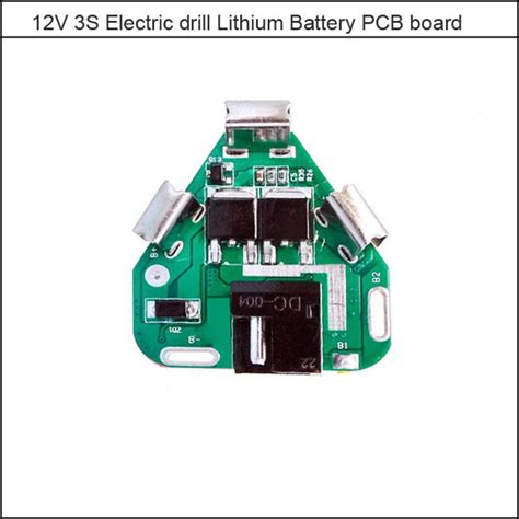
What is a Lithium Battery PCB?
A lithium battery printed circuit board (PCB) is a critical component in the battery management system (BMS) of electric vehicles. The PCB is responsible for monitoring and regulating the charging and discharging of the lithium-ion battery cells that power the electric car.
The lithium battery PCB typically consists of several key components:
- Microcontroller or processor to run the BMS firmware
- Voltage and current sensing circuits to monitor each battery cell
- Cell balancing circuits to ensure all cells are at the same state of charge
- Communication interfaces like CAN bus to transmit battery data
- Power supply and protection circuits
By carefully monitoring and managing the battery, the lithium battery PCB helps ensure safe, reliable, and efficient operation of the electric vehicle’s battery pack over its service life.
Importance of Lithium Battery PCBs in Electric Vehicles
Lithium-ion batteries have become the dominant energy storage technology for electric vehicles due to their high energy density, low self-discharge, and long cycle life compared to other rechargeable battery chemistries. However, lithium-ion cells require precise control and monitoring to operate safely and achieve optimal performance.
This is where the lithium battery PCB plays a critical role. Some of the key functions it enables include:
Battery Monitoring
The BMS constantly monitors key parameters of each individual battery cell, such as:
- Cell voltage
- Pack current
- Battery temperature
By tracking these metrics, the BMS can detect any abnormal conditions, such as over-voltage, over-current, or over-temperature, and take corrective action to prevent damage to the battery.
Cell Balancing
In a large battery pack containing hundreds or thousands of cells in series, manufacturing variations cause small differences in capacity and impedance between cells. Over many charge-discharge cycles, these variations can cause some cells to become overcharged or over-discharged relative to others.
The lithium battery PCB implements cell balancing algorithms to equalize the state of charge across all cells. This is typically accomplished by either dissipating excess energy from higher charged cells through resistors (passive balancing) or redistributing charge between cells (active balancing). Balancing helps prevent any cell from operating outside its safe voltage range.
State Estimation
The BMS uses the voltage, current, and temperature data to estimate key battery states that are not directly measurable, including:
- State of charge (SoC) – percentage of remaining battery capacity
- State of health (SoH) – ability of battery to store and deliver energy relative to when it was new
- State of power (SoP) – maximum power the battery can safely deliver
Accurate estimation of these states is critical for the electric vehicle to determine driving range and optimize energy utilization.
Safety Protection
Lithium-ion batteries can pose safety hazards if operated outside their designed limits. The lithium battery PCB incorporates protection circuits to safeguard against:
- Overcharge – charging voltage too high
- Over-discharge – cell voltage drops too low
- Overcurrent – excessive current during charging or discharging
- Short circuit – cell terminals are shorted due to internal or external faults
- Overheating – battery temperature exceeds safe limit
If any of these fault conditions are detected, the BMS will take immediate action, such as disconnecting the battery from the load or charger, to prevent a potentially catastrophic failure like thermal runaway.

Lithium Battery PCB Design Considerations
Designing a lithium battery PCB for an electric vehicle requires careful consideration of several key factors:
Voltage and Current Rating
The PCB must be rated to handle the maximum voltage and current of the battery pack. Electric vehicle batteries typically operate at voltages of 300-800V and can discharge at currents of hundreds of amps. All components and traces on the PCB must be sized appropriately to handle these high power levels.
Accuracy and Resolution
Precise measurement of cell voltages and pack current is essential for effective battery monitoring and control. The analog front end of the BMS must provide accurate, high-resolution data to the microcontroller. Typical requirements are:
| Component | Accuracy | Resolution |
|---|---|---|
| Cell voltage | ±5 mV | 1 mV |
| Pack current | ±1% | 10 mA |
| Temperature | ±1°C | 0.1°C |
Achieving this level of accuracy requires careful PCB layout to minimize noise and cross-talk, as well as selection of precision components such as reference voltages and current sense amplifiers.
Communication
The lithium battery PCB must communicate with other vehicle systems to report battery status and receive control commands. Common communication interfaces in automotive systems include:
- CAN (Controller Area Network)
- LIN (Local Interconnect Network)
- Ethernet
- FlexRay
The BMS may use multiple communication channels for redundancy and must be designed to meet automotive electromagnetic compatibility (EMC) and electromagnetic interference (EMI) requirements.
Reliability and Durability
Electric vehicle batteries are expected to last the lifetime of the vehicle, typically 8-10 years or more. The lithium battery PCB must be designed for high reliability and durability in the harsh automotive environment, including:
- Wide operating temperature range (-40°C to +85°C)
- Vibration and shock
- Humidity and corrosion
- Dust and debris
Selection of automotive-grade components, conformal coating, and rigorous qualification testing are essential to ensure the PCB can withstand these conditions over the vehicle lifetime.
Safety and Compliance
Lithium battery PCBs for electric vehicles must comply with stringent safety and regulatory standards, such as:
- ISO 26262 – Functional safety standard for road vehicles
- SAE J2929 – Safety standard for electric and hybrid vehicle propulsion battery systems
- UL 2580 – Safety standard for batteries in electric vehicles
- ECE R100 – United Nations regulation on electric vehicle safety
Adherence to these standards requires incorporation of safety features such as:
- Isolation monitoring
- Redundant protection circuits
- Fail-safe design
- Rigorous validation testing

Lithium Battery PCB Manufacturing
Manufacturing lithium battery PCBs for electric vehicles requires specialized capabilities beyond those of standard PCB fabrication and assembly.
Key considerations include:
Materials
The PCB substrate and components must be rated for high voltages and temperatures. Common material choices are:
- FR-4 or polyimide for the PCB laminate
- Copper or aluminum for the conductors
- Ceramic or tantalum for the capacitors
Automotive-grade materials may be required to meet reliability and durability requirements.
Solder Mask and Silkscreen
A clear, high-contrast solder mask and silkscreen are essential for ease of assembly and inspection. White solder mask is often used for improved heat dissipation.
Controlled Impedance
Traces carrying high-speed signals, such as communication buses or PWM (Pulse Width Modulation) controls, may require controlled impedance to ensure signal integrity. This requires precise control of trace width, spacing, and dielectric thickness.
Conformal Coating
A conformal coating, such as acrylic, silicone, or parylene, is typically applied to the assembLED PCB to provide protection against moisture, corrosion, and contaminants.
Testing and Inspection
Rigorous testing and inspection are required at multiple stages of lithium battery PCB manufacturing, including:
- Bare board electrical testing
- In-circuit testing of assembled PCBs
- Functional testing of completed BMS
- Environmental stress testing (temperature, vibration, humidity)
- Accelerated life testing
- X-ray inspection for hidden defects
100% traceability of materials and processes is often required for automotive applications.

Emerging Trends in Lithium Battery PCBs
As electric vehicles continue to evolve, so do the requirements for lithium battery PCBs. Some emerging trends include:
Higher Voltage Systems
To increase driving range and reduce charging time, electric vehicle batteries are moving to higher voltages, such as 800V or even 1000V. This requires lithium battery PCBs to handle higher voltages and currents, driving the need for new materials and design techniques.
Wireless BMS
Some manufacturers are exploring wireless communication between the BMS and individual battery cells, eliminating the need for complex wiring harnesses. This can reduce weight, cost, and assembly time, but requires the lithium battery PCB to incorporate wireless communication capabilities.
Integration with Other Systems
There is a trend towards greater integration of the BMS with other vehicle systems, such as the charger, thermal management, and power electronics. This can provide a more holistic approach to energy management, but requires the lithium battery PCB to interface with a wider range of components and communicate using multiple protocols.
Advanced Analytics
With the proliferation of sensors and data in electric vehicles, there is an opportunity to apply advanced analytics and machine learning techniques to the data collected by the BMS. This can enable predictive maintenance, adaptive control strategies, and enhanced safety features, but requires the lithium battery PCB to have greater processing power and data storage capabilities.
FAQ
What is the difference between a lithium battery PCB and a standard PCB?
A lithium battery PCB is specifically designed to monitor and control a lithium-ion battery pack in an electric vehicle. It must handle high voltages and currents, communicate with other vehicle systems, and meet stringent automotive safety and reliability standards. A standard PCB may not have these capabilities.
How does a lithium battery PCB ensure safety?
A lithium battery PCB incorporates multiple safety features, such as:
- Overvoltage and undervoltage protection
- Overcurrent and short circuit protection
- Temperature monitoring and thermal shutdown
- Isolation monitoring
- Redundant protection circuits
- Fail-safe design
These features help prevent battery failures that could lead to fire or explosion.
What communication protocols are used by lithium battery PCBs?
Common communication protocols used by lithium battery PCBs in electric vehicles include:
- CAN (Controller Area Network)
- LIN (Local Interconnect Network)
- Ethernet
- FlexRay
The specific protocols used may vary depending on the vehicle manufacturer and BMS design.
How long do lithium battery PCBs last in electric vehicles?
Lithium battery PCBs are designed to last the lifetime of the electric vehicle, typically 8-10 years or more. However, the actual lifetime will depend on factors such as the specific operating conditions, battery usage patterns, and manufacturing quality.
Can lithium battery PCBs be recycled?
Yes, lithium battery PCBs can be recycled at the end of their useful life. The PCBs contain valuable metals such as copper, gold, and palladium that can be recovered through specialized recycling processes. Proper recycling helps reduce electronic waste and conserve natural resources.
No responses yet