What is Through-hole Assembly?
Through-hole assembly is a method of mounting electronic components onto a printed circuit board (PCB) by inserting component leads through holes drilled in the board and soldering them to pads on the opposite side. This type of assembly has been used for decades and remains popular for certain applications despite the rise of surface mount technology (SMT).
Advantages of Through-hole Assembly
Through-hole assembly offers several advantages over SMT:
-
Stronger mechanical bonds: The leads passing through the board and soldered on the other side create a robust mechanical connection that can withstand greater physical stress and vibration.
-
Easier manual assembly: Through-hole components are larger and easier to handle, making them suitable for manual assembly or prototyping.
-
Better thermal management: The leads of through-hole components can act as heat sinks, allowing for better heat dissipation compared to SMT components.
-
Higher power handling: Through-hole components can generally handle higher power levels than their SMT counterparts due to their larger size and better thermal management.
Disadvantages of Through-hole Assembly
Despite its advantages, through-hole assembly also has some drawbacks:
-
Lower component density: Through-hole components require more board space, limiting the component density compared to SMT.
-
Higher assembly costs: Drilling holes and manual insertion of components can increase assembly time and costs.
-
Limited component availability: Fewer through-hole components are available as manufacturers shift focus to SMT.
-
Reduced design flexibility: Through-hole components have fixed lead positions, limiting design options compared to SMT.
Through-hole Assembly Process
The through-hole assembly process involves several steps:
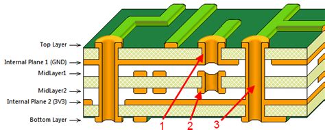
1. PCB Fabrication
The PCB is designed and fabricated with the necessary through-holes for component placement. The holes are typically plated with a conductive material to ensure a good electrical connection.
2. Component Insertion
Through-hole components are inserted into the corresponding holes on the PCB. This can be done manually or using automated insertion machines. Care must be taken to ensure correct component orientation and alignment.
3. Soldering
Once the components are inserted, the board is placed in a Wave Soldering machine or manually soldered. In wave soldering, the board passes over a molten solder wave, which wets the component leads and pads, creating a strong electrical and mechanical bond. Manual soldering involves applying solder to each joint individually using a soldering iron.
4. Inspection and Testing
After soldering, the assembled board undergoes visual inspection to check for any defects, such as bridging, insufficient solder, or misaligned components. Electrical testing is also performed to ensure proper functionality and connectivity.
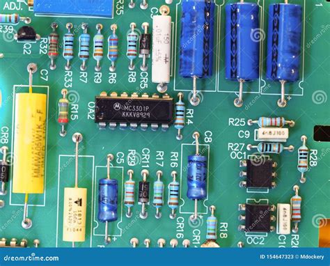
Common Through-hole Components
Many electronic components are available in through-hole packages, including:
- Resistors
- Capacitors
- Inductors
- Diodes
- Transistors
- Integrated circuits (DIP packages)
- Connectors
- Switches

Through-hole vs. Surface Mount Technology
| Aspect | Through-hole | Surface Mount |
|---|---|---|
| Component size | Larger | Smaller |
| Board space | More | Less |
| Component density | Lower | Higher |
| Assembly costs | Higher | Lower |
| Manual assembly | Easier | More difficult |
| Mechanical strength | Stronger | Weaker |
| Thermal management | Better | Worse |
| Power handling | Higher | Lower |
| Component availability | Limited | Wider |
| Design flexibility | Reduced | Greater |
Applications of Through-hole Assembly
Through-hole assembly remains popular in certain applications, such as:
-
High-power electronics: The better thermal management and power handling of through-hole components make them suitable for high-power applications, such as power supplies and Motor Controllers.
-
Prototyping and low-volume production: The ease of manual assembly and the availability of breadboards with through-hole connections make through-hole assembly a popular choice for prototyping and low-volume production.
-
Harsh environments: The stronger mechanical bonds of through-hole components can withstand greater physical stress and vibration, making them suitable for use in harsh environments, such as automotive and industrial applications.
-
Educational and hobby projects: Through-hole components are often used in educational and hobby projects due to their ease of handling and the availability of breadboards and perfboards with through-hole connections.
FAQ
1. Can through-hole and surface mount components be used together on the same PCB?
Yes, it is possible to use both through-hole and surface mount components on the same PCB. This is known as a mixed-technology assembly. However, it is essential to consider the assembly process and ensure compatibility between the two technologies.
2. Are through-hole components becoming obsolete?
While surface mount technology has become more prevalent, through-hole components are not obsolete. They still have specific applications where their advantages, such as stronger mechanical bonds and better thermal management, are valued. However, the availability of through-hole components may decrease as manufacturers focus more on SMT.
3. What is the difference between wave soldering and manual soldering?
Wave soldering is an automated process where the PCB is passed over a molten solder wave, which wets the component leads and pads. This method is faster and more suitable for high-volume production. Manual soldering, on the other hand, involves applying solder to each joint individually using a soldering iron. This method is more time-consuming but offers greater control and is suitable for low-volume production or rework.
4. Can through-hole components be used with lead-free solder?
Yes, through-hole components can be used with lead-free solder. However, lead-free solder typically has a higher melting point than traditional lead-based solder, which may require adjustments to the soldering process, such as higher temperatures or longer dwell times.
5. What are the most common defects in through-hole assembly?
Some of the most common defects in through-hole assembly include:
- Insufficient solder: When not enough solder is applied, resulting in a weak mechanical and electrical connection.
- Bridging: When excess solder creates an unintended connection between adjacent pads or leads.
- Component misalignment: When components are not inserted correctly or shift during the soldering process.
- Tombstoning: When one end of a component lifts off the pad due to uneven heating or surface tension during soldering.
- Cold joints: When the solder fails to properly bond with the component lead or pad, resulting in a brittle and unreliable connection.
Through-hole assembly remains an essential technique in electronics manufacturing, offering unique advantages in specific applications. While surface mount technology has become more popular, through-hole assembly continues to be relevant in high-power electronics, harsh environments, prototyping, and educational projects. By understanding the advantages, disadvantages, and process of through-hole assembly, designers and manufacturers can make informed decisions when choosing the most suitable assembly method for their projects.
No responses yet