What is a Stripline?
A stripline is a type of electrical transmission line that is commonly used in high-frequency circuit design. It consists of a flat conductor strip sandwiched between two parallel ground planes, with a dielectric material filling the space between the conductor and ground planes. Striplines are often used in microwave circuits, such as filters, couplers, and power dividers, due to their excellent electrical characteristics and ability to maintain a constant characteristic impedance over a wide frequency range.
Importance of Characteristic Impedance in Stripline Design
The characteristic impedance of a stripline is a crucial parameter that determines how well the transmission line will perform in a circuit. It is defined as the ratio of the voltage to the current in the stripline when the line is infinitely long and there are no reflections. The characteristic impedance is determined by the geometry of the stripline, including the width of the conductor strip, the thickness of the dielectric material, and the distance between the ground planes.
Maintaining a consistent characteristic impedance throughout a circuit is essential for several reasons:
-
Impedance matching: When the characteristic impedance of a stripline matches the impedance of the components it is connected to, such as a source or load, maximum power transfer occurs, and reflections are minimized. This leads to optimal signal integrity and minimal signal distortion.
-
Reducing reflections: Mismatched impedances cause reflections, which can lead to standing waves, signal distortion, and power loss. By designing striplines with the correct characteristic impedance, reflections can be minimized, ensuring efficient power transfer and maintaining signal quality.
-
Controlling crosstalk: In multi-layer circuits, where multiple striplines are placed close together, maintaining a consistent characteristic impedance helps to reduce crosstalk between adjacent lines. This is because well-matched impedances minimize the coupling of electromagnetic fields between the lines.
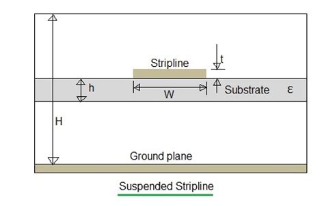
Factors Affecting Stripline Characteristic Impedance
Several factors influence the characteristic impedance of a stripline. Understanding these factors is essential for designing striplines with the desired impedance.
-
Conductor width (w): The width of the conductor strip is one of the most significant factors affecting characteristic impedance. As the conductor width increases, the characteristic impedance decreases. This is because a wider conductor has a lower resistance and a higher capacitance to the ground planes.
-
Dielectric thickness (h): The thickness of the dielectric material between the conductor strip and the ground planes also plays a role in determining characteristic impedance. As the dielectric thickness increases, the characteristic impedance increases. This is because a thicker dielectric reduces the capacitance between the conductor and ground planes.
-
Dielectric constant (εr): The dielectric constant of the material used between the conductor strip and ground planes affects the characteristic impedance. A higher dielectric constant results in a lower characteristic impedance, as it increases the capacitance between the conductor and ground planes.
-
Ground plane spacing (b): The distance between the two ground planes, also known as the stripline height, influences the characteristic impedance. As the ground plane spacing increases, the characteristic impedance decreases, as it reduces the capacitance between the conductor and ground planes.

Stripline Impedance Calculator
To simplify the process of designing striplines with the desired characteristic impedance, engineers often use stripline impedance calculators. These calculators take into account the various factors affecting characteristic impedance and provide a quick and easy way to determine the required stripline dimensions.
A stripline impedance calculator typically requires the following inputs:
- Desired characteristic impedance (Z0)
- Dielectric constant of the substrate material (εr)
- Dielectric thickness (h)
- Conductor thickness (t)
- Ground plane spacing (b)
Based on these inputs, the calculator uses a set of equations to determine the required conductor width (w) to achieve the desired characteristic impedance. The most commonly used equations for calculating stripline characteristic impedance are:
where:
– Z0 is the characteristic impedance
– εr is the dielectric constant
– h is the dielectric thickness
– w is the conductor width
– t is the conductor thickness
The calculator may also provide additional outputs, such as the effective dielectric constant (εeff) and the propagation velocity (vp) of the stripline.
| Input Parameter | Value |
|---|---|
| Z0 (Ω) | 50 |
| εr | 4.3 |
| h (mm) | 0.8 |
| t (mm) | 0.035 |
| b (mm) | 1.6 |
| Output Parameter | Value |
|---|---|
| w (mm) | 0.7952 |
| εeff | 3.3872 |
| vp (m/s) | 1.715 × 10^8 |
Example of a stripline impedance calculator input and output.
Limitations of Stripline Impedance Calculators
While stripline impedance calculators are valuable tools for designing striplines, they have some limitations that engineers should be aware of:
-
Frequency-dependent effects: Stripline impedance calculators typically assume a quasi-static approximation, which means they do not account for frequency-dependent effects such as dispersion and losses. At higher frequencies, these effects can become significant, and the actual characteristic impedance may deviate from the calculated value.
-
Simplified geometry: Calculators often assume a simplified stripline geometry, neglecting factors such as conductor surface roughness, edge effects, and non-ideal dielectric properties. These factors can influence the characteristic impedance, especially at higher frequencies.
-
Manufacturing tolerances: The actual characteristic impedance of a manufactured stripline may vary from the calculated value due to manufacturing tolerances. Variations in conductor width, dielectric thickness, and dielectric constant can all contribute to deviations from the desired impedance.
Despite these limitations, stripline impedance calculators remain an essential tool for initial stripline design. Engineers often use these calculators to obtain a starting point for their designs and then refine the dimensions through simulations and measurements to account for frequency-dependent effects and manufacturing tolerances.
Advanced Stripline Design Considerations
In addition to calculating the characteristic impedance, there are several other factors that engineers must consider when designing striplines for high-frequency applications:
-
Losses: Striplines experience losses due to conductor and dielectric dissipation. These losses increase with frequency and can lead to signal attenuation and distortion. To minimize losses, engineers can use low-loss dielectric materials, such as polytetrafluoroethylene (PTFE) or high-frequency laminates, and choose conductor materials with high conductivity, such as copper or silver.
-
Dispersion: Dispersion occurs when the propagation velocity of a signal varies with frequency. In striplines, dispersion is caused by the frequency-dependent nature of the dielectric constant and the non-ideal behavior of the conductors. Dispersion can lead to signal distortion and limit the usable bandwidth of the stripline. To minimize dispersion, engineers can use dielectric materials with a stable dielectric constant over the desired frequency range and optimize the stripline geometry to reduce non-ideal effects.
-
Discontinuities: Discontinuities in striplines, such as bends, transitions, and junctions, can cause reflections and signal distortion. Engineers must carefully design these discontinuities to minimize their impact on signal integrity. This can involve using gradual transitions, impedance matching techniques, and electromagnetic simulations to optimize the discontinuity geometry.
-
Shielding: In some applications, striplines may need to be shielded from external electromagnetic interference (EMI) or to prevent the stripline from radiating EMI to other parts of the circuit. Shielding can be achieved by using conductive enclosures or by placing the stripline between additional ground planes. However, shielding can also affect the characteristic impedance and propagation velocity of the stripline, so it must be accounted for in the design process.
-
Thermal management: High-power striplines can generate significant amounts of heat due to conductor and dielectric losses. This heat must be efficiently dissipated to prevent thermal damage to the stripline and surrounding components. Engineers can use thermal simulations to predict the temperature distribution in the stripline and design appropriate cooling solutions, such as heat sinks or forced air cooling.
Frequently Asked Questions (FAQ)
-
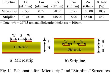
What is the difference between a stripline and a microstrip?
A stripline consists of a conductor strip sandwiched between two parallel ground planes, with a dielectric material filling the space between the conductor and ground planes. In contrast, a microstrip has a single conductor strip on top of a dielectric substrate, with a single ground plane below the substrate. Striplines offer better shielding and lower radiation losses compared to microstrips, but they are more challenging to fabricate and integrate with other components. -
Can I use a stripline impedance calculator for microstrip design?
No, stripline impedance calculators are specifically designed for stripline geometry and cannot be directly applied to microstrip design. Microstrips have different electromagnetic field distributions and characteristic impedance equations compared to striplines. For microstrip design, you should use a dedicated microstrip impedance calculator or consult microstrip design guidelines. -
How accurate are stripline impedance calculators?
Stripline impedance calculators provide a good starting point for stripline design, but their accuracy is limited by the assumptions made in the underlying equations and the simplified geometry used in the calculations. The actual characteristic impedance of a manufactured stripline may deviate from the calculated value due to frequency-dependent effects, manufacturing tolerances, and other factors not accounted for in the calculator. Engineers often use electromagnetic simulations and measurements to refine the stripline design and verify the actual characteristic impedance. -
What is the typical characteristic impedance of a stripline?
The most common characteristic impedance for striplines is 50 ohms, as it provides a good balance between power handling capability, signal integrity, and compatibility with other 50-ohm components and systems. However, striplines can be designed with other characteristic impedances, such as 75 ohms or 100 ohms, depending on the specific application requirements. -
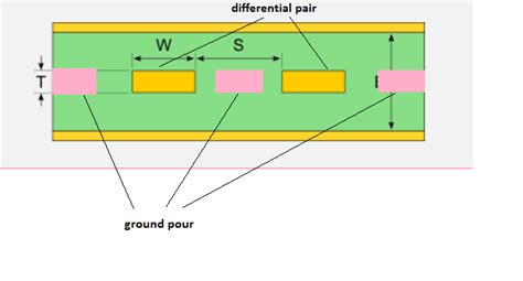
Can I use a stripline impedance calculator for differential striplines?
Stripline impedance calculators are primarily designed for single-ended striplines and do not directly apply to differential striplines. Differential striplines consist of two coupled conductor strips and have additional parameters, such as odd-mode and even-mode impedances, that must be considered in the design process. For differential stripline design, you should use specialized differential stripline calculators or consult differential stripline design guidelines.
Conclusion
Stripline impedance calculators are valuable tools for engineers designing high-frequency circuits. By taking into account the various factors affecting characteristic impedance, such as conductor width, dielectric thickness, and dielectric constant, these calculators provide a quick and easy way to determine the required stripline dimensions for a desired impedance. However, engineers must be aware of the limitations of stripline impedance calculators, such as frequency-dependent effects and manufacturing tolerances, and use them as a starting point for further design refinement through simulations and measurements.
In addition to characteristic impedance, engineers must consider other factors when designing striplines, such as losses, dispersion, discontinuities, shielding, and thermal management. By carefully addressing these factors and using advanced design techniques, engineers can create high-performance striplines that maintain signal integrity and meet the demanding requirements of modern high-frequency applications.
No responses yet