Introduction to the STK500 Development Board
The STK500 is a popular development board and in-system programmer for Atmel AVR microcontrollers. It provides an easy way to program and debug AVR microcontrollers using a USB connection to a computer. The STK500 supports a wide range of AVR devices and has many features that make it a great choice for both beginners and experienced embedded developers.
Key Features of the STK500
The STK500 development board includes the following key features:
- Support for a wide range of Atmel AVR microcontrollers, including the ATmega and ATtiny series
- On-board in-system programming (ISP) capabilities via a USB connection
- RS-232 level converter for serial communication
- 8 LED indicators connected to I/O ports
- 8 push buttons connected to I/O ports
- Analog input channels for testing ADC functionality
- External SRAM socket for memory expansion
- Expansion headers for easy access to microcontroller pins
These features make the STK500 a versatile development platform suitable for many different types of AVR projects.
Getting Started with the STK500
What’s Included
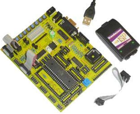
The STK500 development kit comes with everything you need to get started programming AVR microcontrollers:
- STK500 development board
- USB cable for power and in-system programming
- 8 MHz crystal
- Atmel AVR Studio CD containing datasheets, sample code, and development tools
Connecting the STK500
To use the STK500, simply connect it to your computer using the included USB cable. The board will be powered via USB and you will be able to program the on-board AVR microcontroller.
The STK500 has two 6-pin ISP headers, one for the microcontroller and one for any external target board. Make sure to connect your programmer to the correct header depending on what you want to program.
Installing AVR Studio
To program the AVR microcontroller on the STK500, you will need to install Atmel’s AVR Studio development environment on your computer. AVR Studio is an integrated development environment (IDE) that allows you to write, compile, and debug code for AVR microcontrollers.
The AVR Studio CD is included with the STK500, but you can also download the latest version from the Atmel website. Simply run the installer and follow the on-screen instructions. Once installation is complete, launch AVR Studio to get started.

Programming with the STK500
Creating a New Project
To create a new project in AVR Studio for the STK500:
- Go to File > New Project
- Select “Atmel STK500” as the debugging tool and click “Next”
- Choose your microcontroller device from the list and click “Finish”
AVR Studio will create a new project targeting the STK500 and selected device. You can now start writing your code in the editor.
Compiling and Uploading Code
When you are ready to compile your code, simply click the “Build” button in AVR Studio. If there are no errors, you can then upload the code to the microcontroller on the STK500 by clicking “Debug”.
AVR Studio will launch the AVR ISP programming dialog. Make sure the STK500 is selected as the programmer and the correct microcontroller settings are chosen. Then click “Program” to upload your compiled code to the device. You should see the LED indicators on the STK500 respond as your code executes.
Debugging with the STK500
One of the key advantages of using the STK500 is the ability to debug your code directly on the hardware. AVR Studio provides a full-featured debugger that allows you to step through your code, set breakpoints, and inspect variable values.
To start a debugging session, click the “Debug” button in AVR Studio with the STK500 selected as the programmer. The debugger will pause execution at the first line of your code. From there you can use the debug controls to step through the program and analyze its behavior.

Example STK500 Projects
To help illustrate how to use the STK500, let’s walk through a couple example projects. These examples will demonstrate some of the capabilities of the board and how to interface with various peripherals.
Project 1: Blinking an LED
A simple first project is to blink one of the on-board LEDs on the STK500. This will demonstrate how to control I/O pins on the microcontroller. Here are the steps:
-
Create a new project in AVR Studio targeting your AVR device on the STK500.
-
Use the following code to blink the LED on I/O pin PB0 at a 1 Hz rate:
#include <avr/io.h>
#include <util/delay.h>

#define LED_PIN PB0

int main (void)
{
  DDRB |= (1 << LED_PIN);  // Set LED pin as an output

  while(1) {
    PORTB |= (1 << LED_PIN);   // Turn LED on
    _delay_ms(500);        // Delay 500 ms

    PORTB &= ~(1 << LED_PIN);  // Turn LED off
    _delay_ms(500);        // Delay 500 ms
  }
}
-
Compile the code and upload it to the STK500 using AVR Studio.
-
The LED connected to pin PB0 should now be blinking at a rate of 1 Hz.
This simple example demonstrates the basic structure of an AVR program and how to manipulate I/O pins to interface with external hardware like an LED. The STK500 makes it easy to experiment with this type of low-level hardware control.
Project 2: Reading a Push Button
Next let’s look at an example that reads the state of a push button and turns on an LED when the button is pressed. This project will show how to configure an I/O pin as an input and use it to control the state of an output. Here’s how to set it up:
-
Create a new project in AVR Studio for the STK500 as before.
-
Connect a push button between I/O pin PD0 and ground on the STK500. The development board already has pull-up resistors on the I/O pins, so no external resistors are needed.
-
Use the following code to read the button state and light the LED on PB0 when pressed:
#include <avr/io.h>

#define LED_PIN PB0
#define BUTTON_PIN PD0

int main (void)
{
  DDRB |= (1 << LED_PIN);    // Set LED pin as output
  DDRD &= ~(1 << BUTTON_PIN);  // Set button pin as input

  while(1) {
    if (PIND & (1 << BUTTON_PIN)) {  // If button is not pressed
      PORTB &= ~(1 << LED_PIN);   // Turn LED off
    } else {           // If button is pressed
      PORTB |= (1 << LED_PIN);    // Turn LED on
    }
  }
}
-
Compile and upload the code to the STK500.
-
Press and hold the push button – the LED should light up. Release the button and the LED will turn off.
This example shows how to configure an AVR I/O pin as an input and read its state. By connecting a push button, we can use the input state to control an output pin and light an LED. The STK500 makes it easy to wire up simple circuits like this and test out the code.

Interfacing Other Hardware with the STK500
Beyond simple inputs and outputs, the STK500 also includes other hardware that can be used to interface with external circuits and devices. Some examples include:
Serial Communication
The STK500 includes a RS-232 level converter that allows you to communicate with the microcontroller over a serial connection. Simply connect the RXD and TXD pins on the converter to the corresponding UART pins on the microcontroller with jumper wires.
In your code, you can then use the built-in UART library functions to send and receive data over the serial port. For example:
#include <avr/io.h>
#include <util/setbaud.h>

void setup_uart(void) {
  UBRR0H = UBRRH_VALUE;
  UBRR0L = UBRRL_VALUE;

  UCSR0B = (1<<RXEN0) | (1<<TXEN0);
  UCSR0C = (1<<UCSZ01) | (1<<UCSZ00);
}

void uart_tx(char c) {
  while (!( UCSR0A & (1<<UDRE0)));
  UDR0 = c;
}

int main(void)
{
  char msg[] = "Hello World!\r\n";
  int i;

  setup_uart();

  while(1) {
    for(i=0; msg[i] != 0; i++) {
      uart_tx(msg[i]);
    }
  }
}
This code sets up the UART and continuously transmits a “Hello World!” message over the serial port. You can view the output in AVR Studio’s built-in terminal window.
Analog Input
The STK500 has several analog input channels that are connected to the AVR’s ADC module. To read an analog voltage, simply connect it to one of the analog input pins and use the ADC library to sample the voltage.
For example, to read the voltage on analog input 0 and light an LED if it exceeds a threshold:
#include <avr/io.h>

#define LED_PIN PB0
#define THRESHOLD 512

void setup_adc(void) {
  ADMUX = (1<<REFS0);
  ADCSRA = (1<<ADEN) | (1<<ADPS2) | (1<<ADPS1) | (1<<ADPS0);
}

uint16_t read_adc(void) {
  ADCSRA |= (1<<ADSC);
  while(ADCSRA & (1<<ADSC));
  return ADC;
}

int main(void) {
  uint16_t value;

  DDRB |= (1 << LED_PIN);
  setup_adc();

  while(1) {
    value = read_adc();
    if(value > THRESHOLD) {
      PORTB |= (1 << LED_PIN);
    } else {
      PORTB &= ~(1 << LED_PIN);
    }
  }
}
This samples the voltage on analog pin 0 and lights the LED if it is greater than 512 (2.5V with a 5V reference). You can experiment with connecting different sensors to the analog inputs to measure things like temperature, light, or motion.
External Memory
The STK500 has a socket for connecting an external SRAM chip to expand the memory available to the microcontroller. This can be useful for data logging or buffering large amounts of data.
To use external memory, you will need to insert a compatible SRAM chip into the socket and wire the address and Data Buses to the correct pins on the microcontroller. Consult the datasheet for your specific memory chip for connection information.
In your code, you can then use special functions to read and write data to the external memory, similar to accessing internal SRAM. For example, to write a byte to external memory:
#include <avr/io.h>
#include <avr/pgmspace.h>

void mem_write(uint8_t data, uint16_t addr) {
  MCUCR |= (1<<SRE);
  SFIOR |= (1<<XMM2);

  volatile uint8_t *ext_mem = (uint8_t *)(0x2000 + addr);
  *ext_mem = data;

  MCUCR &= ~(1<<SRE);
  SFIOR &= ~(1<<XMM2);
}
And to read a byte from external memory:
uint8_t mem_read(uint16_t addr) {
  MCUCR |= (1<<SRE);
  SFIOR |= (1<<XMM2);

  volatile uint8_t *ext_mem = (uint8_t *)(0x2000 + addr);
  uint8_t data = *ext_mem;

  MCUCR &= ~(1<<SRE);
  SFIOR &= ~(1<<XMM2);

  return data;
}
Using external memory can significantly increase the storage capabilities of your AVR project when using the STK500.
Advanced STK500 Features
In addition to the hardware interfaces described above, the STK500 has a few other useful features for developing AVR projects:
In-System Programming (ISP)
The STK500 supports in-system programming of the target AVR microcontroller. This allows you to reprogram the chip without removing it from the development board. Simply connect the 6-pin ISP header to your programmer and upload new code directly.
To use ISP, select “Atmel STK500” as the programmer in AVR Studio when uploading your code. You may need to set the ISP frequency to a lower value for reliable programming, especially with slower crystal speeds.
JTAG Debugging
For more advanced debugging capabilities, the STK500 also supports JTAG in-circuit emulation. By connecting a JTAG adapter to the JTAG header on the board, you can use a hardware debugger to step through code, set breakpoints, and view memory contents in real-time.
To use JTAG with AVR Studio, select “AVR JTAGICE mkII” as the debugger platform and connect your JTAG adapter to the JTAG header. You can then use the full debugging features of the IDE to analyze your code’s behavior on the STK500.
Expansion Headers
The STK500 includes several expansion headers that provide access to all of the microcontroller’s I/O pins. You can use these headers to easily connect additional hardware, like sensors, displays, or actuators.
The expansion headers are arranged in the standard 100-mil spacing, so they are compatible with a wide variety of prototyping boards and accessories. Simply consult the STK500 schematic to determine the pinout of the expansion headers and wire up your external hardware accordingly.
Troubleshooting Common Issues
While the STK500 is generally easy to use, there are a few common issues that you may encounter. Here are some troubleshooting tips:
USB Driver Not Recognized
If your computer does not recognize the STK500 when connected via USB, you may need to install the appropriate drivers. Check that you have the latest version of AVR Studio installed, as it includes the necessary drivers.
If you are still having issues, try a different USB cable or port. You can also try manually installing the drivers from the Atmel website.
Programming Errors
If you encounter errors when trying to upload code to the STK500, there are a few things to check:
- Make sure you have selected the correct programmer type (Atmel STK500) and microcontroller device in AVR Studio.
- Check that the ISP frequency is set to an appropriate value for your crystal speed. Higher frequencies may cause programming errors.
- Verify that your code compiles without errors and that you are uploading the correct .hex file.
- If using an external target board, ensure that it is properly connected to the ISP header and that it has a compatible pinout.
Debugging Issues
If you are having trouble debugging your code on the STK500, here are a few things to try:
- Verify that your code compiles without errors and that you are uploading the correct .hex file.
- Make sure you have selected the correct debugger type (AVR JTAGICE mkII) and microcontroller device in AVR Studio.
- Check that your JTAG adapter is properly connected to the JTAG header on the STK500 and that it is powered on.
- Try reducing the JTAG frequency if you are experiencing communication errors or lockups.
By following these troubleshooting tips, you should be able to resolve most common issues with the STK500.
STK500 FAQs
Q: What microcontrollers are supported by the STK500?
A: The STK500 supports a wide range of Atmel AVR microcontrollers, including the ATmega and ATtiny series. Consult the STK500 documentation for a full list of supported devices.
Q: Can the STK500 be used with other programming environments besides AVR Studio?
A: Yes, the STK500 can be used with other IDEs and programming tools that support Atmel AVR devices. However, using AVR Studio is recommended as it includes built-in support for the STK500 and provides a complete development environment.
Q: How do I use
No responses yet