Introduction to Rigid-Flex PCBs
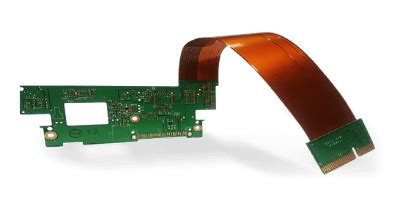
Rigid-Flex PCBs are a combination of rigid and flexible printed circuit boards that offer unique advantages over traditional PCBs. They consist of rigid PCB sections connected by flexible PCB sections, allowing for three-dimensional packaging and improved reliability in applications that require flexibility or space savings.
Advantages of Rigid-Flex PCBs
- Space savings: Rigid-flex PCBs enable more compact packaging by eliminating connectors and allowing for three-dimensional layouts.
- Improved reliability: The reduction of connectors and the use of flexible sections reduce the risk of connection failures and improve overall reliability.
- Increased design flexibility: Rigid-flex PCBs allow for unique form factors and packaging solutions that are not possible with traditional rigid PCBs.
- Reduced assembly time and cost: By eliminating connectors and simplifying assembly, rigid-flex PCBs can reduce manufacturing time and costs.
Rigid-Flex PCB Design Considerations
Materials Selection
Choosing the right materials is crucial for the performance and reliability of rigid-flex PCBs. Key considerations include:
- Flexible substrate materials: Polyimide and polyester are common choices for the flexible sections of rigid-flex PCBs due to their excellent mechanical and electrical properties.
- Adhesives: Selecting the appropriate adhesive for bonding the flexible and rigid sections is essential for ensuring reliable performance.
- Copper type and thickness: The choice of copper type (electrodeposited or rolled annealed) and thickness impacts the flexibility and signal integrity of the PCB.
Stackup Design
A well-designed stackup is critical for optimizing the performance and reliability of rigid-flex PCBs. Factors to consider include:
- Layer count: Determining the appropriate number of layers for both rigid and flexible sections based on the application requirements.
- Copper weight: Selecting the appropriate copper weight for each layer to ensure signal integrity and manufacturability.
- Dielectric thickness: Choosing the right dielectric thickness for each layer to maintain controlled impedance and minimize signal loss.
Flexible Section Design
Designing the flexible sections of a rigid-flex PCB requires careful consideration of several factors:
- Bend radius: Ensuring that the minimum bend radius is maintained to prevent damage to the flexible sections during use.
- Coverlay design: Selecting the appropriate coverlay material and thickness to protect the flexible sections and maintain flexibility.
- Stiffener design: Incorporating stiffeners in the flexible sections to provide support and prevent excessive bending.

Rigid-Flex Optimization Techniques
Signal Integrity Optimization
Maintaining signal integrity is essential for ensuring reliable performance in rigid-flex PCBs. Techniques for optimizing signal integrity include:
- Impedance control: Designing the PCB Stackup and trace geometries to maintain consistent impedance throughout the board.
- Length matching: Ensuring that critical signal paths have matched lengths to minimize skew and maintain signal integrity.
- Shielding: Incorporating shielding techniques, such as ground planes and via fencing, to reduce crosstalk and electromagnetic interference (EMI).
Thermal Management
Proper thermal management is crucial for maintaining the reliability and performance of rigid-flex PCBs. Strategies for improving thermal management include:
- Thermal vias: Incorporating thermal vias to conduct heat away from hot spots and improve heat dissipation.
- Thermal interface materials: Using thermal interface materials, such as thermal pads or thermal adhesives, to enhance heat transfer between components and the PCB.
- Copper pours: Utilizing copper pours on the outer layers of the PCB to improve heat spreading and dissipation.
Mechanical Stress Reduction
Minimizing mechanical stress is essential for ensuring the long-term reliability of rigid-flex PCBs. Techniques for reducing mechanical stress include:
- Strain relief: Incorporating strain relief features, such as curved traces or accordion folds, in the flexible sections to minimize stress during bending.
- Stiffener placement: Optimizing the placement of stiffeners in the flexible sections to provide support and reduce stress concentrations.
- Adhesive selection: Choosing adhesives with appropriate mechanical properties to ensure reliable bonding between the flexible and rigid sections.

Manufacturing Considerations
Fabrication Process
Understanding the fabrication process for rigid-flex PCBs is essential for ensuring manufacturability and reliability. Key steps in the fabrication process include:
- Flexible substrate preparation: Cleaning and treating the flexible substrate to ensure proper adhesion and performance.
- Lamination: Bonding the flexible and rigid sections together using appropriate adhesives and lamination techniques.
- Drilling and plating: Creating and plating the through-holes and vias to establish electrical connections between layers.
- Etching and patterning: Removing unwanted copper to create the desired circuit patterns on each layer.
Assembly Process
Proper assembly techniques are critical for ensuring the reliability and performance of rigid-flex PCBs. Important considerations for the assembly process include:
- Solder mask application: Applying solder mask to protect the exposed copper and prevent short circuits during assembly.
- Component placement: Ensuring accurate placement of components on both the rigid and flexible sections of the PCB.
- Soldering: Using appropriate soldering techniques, such as reflow or wave soldering, to establish reliable connections between components and the PCB.
- Inspection and testing: Conducting thorough inspections and testing to verify the quality and functionality of the assembled PCB.

Case Studies
Case Study 1: Wearable Medical Device
A wearable medical device manufacturer implemented a rigid-flex PCB design to create a compact, lightweight, and reliable device for continuous patient monitoring. By using a rigid-flex PCB, the manufacturer was able to:
- Reduce the overall size of the device by 40% compared to a traditional rigid PCB design.
- Eliminate connectors between the sensor and processing modules, improving reliability and reducing the risk of connection failures.
- Achieve a 50% reduction in assembly time and costs by simplifying the manufacturing process.
Case Study 2: Automotive Electronics
An automotive electronics supplier utilized a rigid-flex PCB design to create a high-performance, space-saving control module for a new vehicle platform. The rigid-flex PCB allowed the supplier to:
- Integrate multiple functions into a single, compact module, reducing the overall space requirements by 30%.
- Improve signal integrity and reduce EMI by incorporating shielding techniques and optimizing the PCB stackup.
- Enhance the module’s reliability by minimizing the number of connectors and utilizing strain relief features in the flexible sections.
Frequently Asked Questions (FAQ)
1. What are the main advantages of using rigid-flex PCBs over traditional rigid PCBs?
Rigid-flex PCBs offer several advantages over traditional rigid PCBs, including space savings, improved reliability, increased design flexibility, and reduced assembly time and costs. By combining rigid and flexible sections, rigid-flex PCBs enable more compact packaging, eliminate the need for connectors, and allow for unique form factors that are not possible with rigid PCBs alone.
2. What materials are commonly used for the flexible sections of rigid-flex PCBs?
Polyimide and polyester are two of the most common materials used for the flexible sections of rigid-flex PCBs. These materials are chosen for their excellent mechanical and electrical properties, including high flexibility, durability, and resistance to temperature and chemicals. The choice of material depends on the specific application requirements, such as the desired bend radius, operating temperature range, and environmental factors.
3. How can signal integrity be optimized in rigid-flex PCBs?
Signal integrity in rigid-flex PCBs can be optimized through a combination of techniques, including:
- Impedance control: Designing the PCB stackup and trace geometries to maintain consistent impedance throughout the board.
- Length matching: Ensuring that critical signal paths have matched lengths to minimize skew and maintain signal integrity.
- Shielding: Incorporating shielding techniques, such as ground planes and via fencing, to reduce crosstalk and electromagnetic interference (EMI).
Additionally, careful selection of materials, such as low-loss dielectrics and high-quality copper, can help minimize signal loss and improve overall signal integrity.
4. What are some key considerations for the manufacturing and assembly of rigid-flex PCBs?
When manufacturing and assembling rigid-flex PCBs, several key factors must be considered to ensure reliability and performance:
- Fabrication process: Proper preparation of the flexible substrate, lamination of the rigid and flexible sections, drilling and plating of through-holes and vias, and etching and patterning of the circuit layers.
- Assembly process: Accurate application of solder mask, precise component placement, appropriate soldering techniques, and thorough inspection and testing.
Choosing experienced and qualified manufacturers with a proven track record in rigid-flex PCB fabrication and assembly is essential for ensuring the highest quality and reliability of the final product.
5. How can mechanical stress be reduced in rigid-flex PCBs?
Mechanical stress in rigid-flex PCBs can be reduced through various design and manufacturing techniques, such as:
- Strain relief: Incorporating strain relief features, such as curved traces or accordion folds, in the flexible sections to minimize stress during bending.
- Stiffener placement: Optimizing the placement of stiffeners in the flexible sections to provide support and reduce stress concentrations.
- Adhesive selection: Choosing adhesives with appropriate mechanical properties to ensure reliable bonding between the flexible and rigid sections.
Additionally, proper handling and installation procedures during assembly and use can help minimize mechanical stress and ensure the long-term reliability of the rigid-flex PCB.
Conclusion
Rigid-flex PCBs offer numerous advantages over traditional rigid PCBs, including space savings, improved reliability, and increased design flexibility. By carefully considering design factors such as materials selection, stackup design, and flexible section layout, engineers can optimize the performance and reliability of rigid-flex PCBs. Additionally, implementing signal integrity optimization, thermal management, and mechanical stress reduction techniques can further enhance the overall performance and longevity of these versatile circuit boards.
As demonstrated by the case studies, rigid-flex PCBs have proven to be valuable solutions in various industries, from medical devices to automotive electronics. By leveraging the benefits of rigid-flex technology and following best practices for design, manufacturing, and assembly, engineers can create high-performance, reliable, and space-efficient electronic products that meet the evolving needs of today’s market.
No responses yet