Introduction to PCB Troubleshooting
Printed Circuit Boards (PCBs) are essential components in modern electronics. They provide a reliable and efficient way to connect electronic components and create complex circuits. However, like any other electronic device, PCBs can experience problems that affect their performance and functionality.
PCB troubleshooting is the process of identifying and resolving issues that arise in PCBs. It involves a systematic approach to testing, analyzing, and repairing the board to restore its functionality. In this article, we will discuss the common problems that can occur in PCBs and provide a comprehensive guide on how to troubleshoot and resolve them.
Common PCB Problems
1. Short Circuits
Short circuits occur when two or more points on a PCB that should not be connected are accidentally connected. This can happen due to various reasons such as:
- Solder bridges: Excess solder can create a connection between two adjacent pads or traces.
- Damaged insulation: If the insulation between two traces is damaged, it can lead to a short circuit.
- Conductive debris: Small pieces of conductive material, such as metal shavings, can create a short circuit if they come into contact with the PCB.
Short circuits can cause a variety of issues, including:
- Overheating: When a short circuit occurs, it can cause excessive current flow, which can lead to overheating of components and even fire.
- Malfunctioning: Short circuits can cause the circuit to behave erratically or not function at all.
- Damage to components: Excessive current flow can damage sensitive components such as ICs and transistors.
To troubleshoot short circuits, you can use a multimeter to measure the resistance between various points on the PCB. If the resistance is lower than expected, it indicates a short circuit. You can also visually inspect the PCB for any obvious signs of damage or debris.
To fix short circuits, you can:
- Remove any excess solder using a solder sucker or desoldering braid.
- Repair any damaged insulation using conformal coating or insulating tape.
- Clean the PCB thoroughly to remove any conductive debris.
2. Open Circuits
Open circuits occur when there is a break in the connection between two points on a PCB. This can happen due to various reasons such as:
- Broken traces: Physical damage to the PCB can cause traces to break, resulting in an open circuit.
- Poor soldering: If a component is not soldered properly, it can result in a poor or no connection.
- Damaged components: If a component is damaged, it can cause an open circuit.
Open circuits can cause the following issues:
- No functionality: If a critical component is not connected, the circuit may not function at all.
- Intermittent functionality: If the connection is poor, the circuit may work intermittently or erratically.
To troubleshoot open circuits, you can use a multimeter to measure the continuity between various points on the PCB. If there is no continuity, it indicates an open circuit. You can also visually inspect the PCB for any obvious signs of damage or poor soldering.
To fix open circuits, you can:
- Repair any broken traces using jumper wires or conductive paint.
- Resolder any poorly soldered components.
- Replace any damaged components.
3. Faulty Components
Faulty components are another common issue in PCBs. Components can fail due to various reasons such as:
- Overheating: Excessive heat can cause components to fail or degrade over time.
- Electrostatic discharge (ESD): ESD can damage sensitive components such as ICs and transistors.
- Aging: Components can degrade over time due to normal wear and tear.
Faulty components can cause a variety of issues, including:
- No functionality: If a critical component is faulty, the circuit may not function at all.
- Erratic behavior: Faulty components can cause the circuit to behave erratically or unpredictably.
- Overheating: Faulty components can draw excessive current, leading to overheating.
To troubleshoot faulty components, you can:
- Visually inspect the components for any signs of damage or overheating.
- Use a multimeter to test the components for proper functionality.
- Compare the measured values with the expected values from the datasheet.
To fix faulty components, you can:
- Replace the faulty component with a new one.
- Ensure proper handling and storage of components to prevent ESD damage.
- Use heat sinks or cooling fans to prevent overheating.
4. Improper Power Supply
An improper power supply can cause various issues in PCBs. This can happen due to:
- Incorrect voltage: If the voltage supplied to the PCB is too high or too low, it can cause components to malfunction or fail.
- Noise: Electrical noise from the power supply can interfere with the functioning of sensitive components.
- Insufficient current: If the power supply cannot provide enough current, it can cause the circuit to malfunction or fail.
Improper power supply can cause the following issues:
- No functionality: If the voltage is too low, the circuit may not function at all.
- Overheating: If the voltage is too high, it can cause components to overheat and fail.
- Erratic behavior: Electrical noise can cause the circuit to behave erratically or unpredictably.
To troubleshoot improper power supply, you can:
- Use a multimeter to measure the voltage at various points on the PCB.
- Check the power supply for any signs of damage or malfunction.
- Use an oscilloscope to check for any electrical noise.
To fix improper power supply, you can:
- Ensure that the power supply is providing the correct voltage and current.
- Use voltage regulators to ensure a stable voltage supply.
- Use filtering capacitors to reduce electrical noise.
5. Overheating
Overheating is a common issue in PCBs that can cause various problems. It can happen due to:
- Excessive current draw: If a component is drawing too much current, it can overheat and fail.
- Inadequate cooling: If the PCB is not properly cooled, it can overheat and cause components to fail.
- High ambient temperature: If the PCB is used in a high-temperature environment, it can overheat and cause components to fail.
Overheating can cause the following issues:
- Component failure: Overheating can cause components to fail prematurely.
- Reduced lifespan: Overheating can reduce the lifespan of components and the PCB as a whole.
- Fire hazard: In extreme cases, overheating can cause a fire hazard.
To troubleshoot overheating, you can:
- Use a thermal camera or temperature probe to identify hot spots on the PCB.
- Check for any components that are drawing excessive current.
- Ensure proper cooling by using heat sinks, fans, or other cooling methods.
To fix overheating, you can:
- Replace any components that are drawing excessive current.
- Improve cooling by adding heat sinks, fans, or other cooling methods.
- Reduce the ambient temperature by using air conditioning or other cooling methods.
PCB Troubleshooting Techniques
Visual Inspection
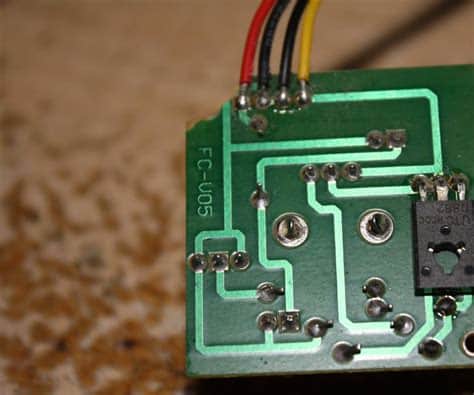
Visual inspection is the first step in PCB troubleshooting. It involves carefully examining the PCB for any obvious signs of damage or defects. This can include:
- Broken or damaged components
- Burnt or discolored components
- Damaged or broken traces
- Solder bridges or poor soldering
- Contamination or debris on the PCB
Visual inspection can help identify many common issues quickly and easily. It is important to use proper lighting and magnification to ensure that all defects are identified.
Continuity Testing
Continuity testing involves using a multimeter to check for continuity between two points on the PCB. This can help identify open circuits or broken traces. To perform continuity testing:
- Set the multimeter to the continuity or resistance mode.
- Place one probe on one end of the trace or component.
- Place the other probe on the other end of the trace or component.
- If the multimeter beeps or shows a low resistance, there is continuity. If there is no beep or a high resistance, there is an open circuit.
Continuity testing can help identify open circuits quickly and easily. It is important to ensure that the multimeter probes are making good contact with the PCB and that the PCB is powered off during testing.
Power Supply Testing
Power supply testing involves using a multimeter to measure the voltage and current supplied to the PCB. This can help identify issues with the power supply or improper voltage or current. To perform power supply testing:
- Set the multimeter to the voltage or current mode.
- Place the probes on the power supply pins or connectors.
- Measure the voltage and current and compare them to the expected values.
- If the voltage or current is too high or too low, there may be an issue with the power supply.
Power supply testing can help identify issues with the power supply quickly and easily. It is important to ensure that the multimeter probes are making good contact with the power supply pins or connectors and that the PCB is powered on during testing.
Signal Tracing
Signal tracing involves using an oscilloscope to trace the signal path through the PCB. This can help identify issues with signal integrity or timing. To perform signal tracing:
- Connect the oscilloscope probe to the signal pin or trace.
- Adjust the oscilloscope settings to display the signal accurately.
- Trace the signal path through the PCB and look for any abnormalities or distortions.
- Compare the signal to the expected waveform and timing.
Signal tracing can help identify issues with signal integrity or timing that may not be visible with other testing methods. It is important to use proper probing techniques and to ensure that the oscilloscope is set up correctly.
Thermal Imaging
Thermal imaging involves using a thermal camera to identify hot spots on the PCB. This can help identify components that are overheating or drawing excessive current. To perform thermal imaging:
- Power on the PCB and let it run for a few minutes.
- Use the thermal camera to scan the PCB and look for any hot spots.
- Identify the components that are generating the most heat.
- Compare the temperatures to the expected values from the datasheet.
Thermal imaging can help identify overheating issues quickly and easily. It is important to ensure that the PCB is powered on and that the thermal camera is set up correctly.

PCB Troubleshooting Tips
- Always start with a visual inspection before performing any other testing.
- Use proper ESD protection when handling PCBs and components.
- Ensure that all test equipment is properly calibrated and set up.
- Take notes and document all testing and repairs.
- Work systematically and methodically to identify and resolve issues.
- Consult the schematic and datasheet when troubleshooting.
- Use proper safety precautions when working with high voltages or currents.
FAQ
1. What are the most common causes of PCB failure?
The most common causes of PCB failure include:
- Improper handling or storage
- Exposure to extreme temperatures or humidity
- Mechanical stress or damage
- Electrostatic discharge (ESD)
- Contamination or debris on the PCB
- Improper power supply or voltage
- Component failure or degradation
2. How can I prevent PCB failures?
To prevent PCB failures, you can:
- Use proper ESD protection when handling PCBs and components
- Store PCBs in a cool, dry environment
- Avoid exposing PCBs to extreme temperatures or humidity
- Use proper packaging and handling techniques to avoid mechanical damage
- Ensure proper power supply and voltage regulation
- Use high-quality components and materials
- Perform regular maintenance and cleaning
3. What tools do I need for PCB troubleshooting?
The essential tools for PCB troubleshooting include:
- Multimeter
- Oscilloscope
- Logic analyzer
- Soldering iron and desoldering tools
- Magnifying glass or microscope
- ESD-safe tweezers and pliers
- Thermal camera or temperature probe
4. How do I identify a faulty component on a PCB?
To identify a faulty component on a PCB, you can:
- Visually inspect the component for any signs of damage or overheating
- Use a multimeter to test the component for proper functionality
- Compare the measured values with the expected values from the datasheet
- Use an oscilloscope to check for any abnormal signals or waveforms
- Use a thermal camera to identify any hot spots on the component
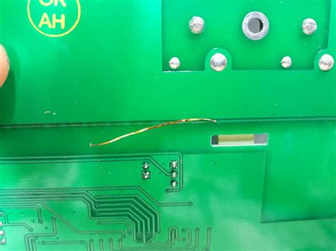
5. Can I repair a damaged PCB trace?
Yes, you can repair a damaged PCB trace using various methods such as:
- Soldering a jumper wire across the damaged trace
- Using conductive ink or paint to bridge the gap
- Scraping away the solder mask and soldering a new trace
- Using a PCB repair kit or conductive adhesive
However, it is important to note that repairing a damaged trace may not always be feasible or cost-effective, especially for complex or multilayer PCBs. In some cases, it may be necessary to replace the entire PCB.
Conclusion
PCB troubleshooting is an essential skill for anyone working with electronics. By understanding the common issues that can arise in PCBs and how to troubleshoot them, you can quickly and effectively identify and resolve problems.
Remember to always start with a visual inspection and work systematically through the various testing methods. Use proper safety precautions and ESD protection, and consult the schematic and datasheet when needed.
With practice and experience, PCB troubleshooting can become a valuable tool in your electronics toolkit. By following the tips and techniques outlined in this article, you can keep your PCBs running smoothly and avoid costly downtime and repairs.
No responses yet