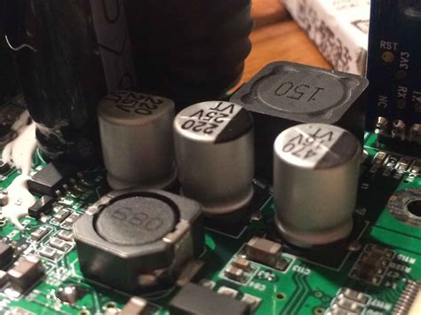
What is a PCB Capacitor?
A PCB capacitor is a passive electronic component that stores electrical energy in an electric field between two conducting plates separated by a dielectric material. Capacitors are widely used in printed circuit boards (PCBs) to perform various functions, such as smoothing power supply ripples, filtering unwanted noise, and providing temporary energy storage.
Key Characteristics of PCB Capacitors
PCB capacitors are characterized by several key parameters:
- Capacitance: Measured in farads (F), capacitance determines the amount of electrical charge a capacitor can store.
- Voltage Rating: The maximum voltage a capacitor can withstand without breakdown.
- Equivalent Series Resistance (ESR): The internal resistance of a capacitor that affects its efficiency and high-frequency performance.
- Dissipation Factor (DF): A measure of a capacitor’s energy loss due to dielectric and resistive losses.
- Temperature Coefficient: The change in capacitance with respect to temperature.
- Leakage Current: The small current that flows through the dielectric when a voltage is applied.
Types of PCB Capacitors
There are several types of PCB capacitors, each with unique characteristics and applications:
Ceramic Capacitors
Ceramic capacitors are the most commonly used type in PCBs due to their low cost, small size, and excellent high-frequency performance. They are available in various dielectric materials, such as X7R, X5R, and NP0 (C0G), each with specific temperature and capacitance stability characteristics.
| Dielectric | Temperature Range | Capacitance Change |
|---|---|---|
| X7R | -55°C to +125°C | ±15% |
| X5R | -55°C to +85°C | ±15% |
| NP0 (C0G) | -55°C to +125°C | ±30 ppm/°C |
Tantalum Capacitors
Tantalum capacitors offer high capacitance values in a small package, making them suitable for applications requiring bulk energy storage and low-frequency filtering. They have a solid tantalum anode and a solid manganese dioxide cathode, separated by a tantalum pentoxide dielectric.
Aluminum Electrolytic Capacitors
Aluminum electrolytic capacitors provide the highest capacitance values among PCB capacitors but have higher ESR and leakage current compared to other types. They are polarized and must be connected with the correct polarity to avoid damage. Aluminum electrolytic capacitors are commonly used in power supply filtering and low-frequency decoupling.
Film Capacitors
Film capacitors, such as polypropylene and polyester types, offer excellent stability, low losses, and high voltage ratings. They are often used in high-frequency applications, such as RF circuits and switch-mode power supplies.
Selecting the Right PCB Capacitor
Choosing the appropriate PCB capacitor depends on several factors:
- Application Requirements: Consider the specific needs of your circuit, such as frequency response, voltage rating, and temperature range.
- Capacitance Value: Determine the required capacitance based on the desired filtering, decoupling, or energy storage performance.
- Package Size: Choose a capacitor package that fits the available PCB space and meets the required mechanical and thermal specifications.
- Cost and Availability: Consider the cost and availability of different capacitor types and values to optimize your design for production.

Best Practices for PCB Capacitor Placement and Routing
Proper placement and routing of PCB capacitors are crucial for optimal performance and signal integrity:
- Minimize Lead Length: Place capacitors as close as possible to the devices they are decoupling or filtering to minimize parasitic inductance.
- Use Wide Traces: Use wide, low-impedance traces to connect capacitors to power and ground planes to reduce series resistance.
- Avoid Vias: Minimize the use of vias in capacitor connections to reduce parasitic inductance and resistance.
- Consider High-Frequency Effects: Use appropriate layout techniques, such as ground planes and power planes, to minimize high-frequency noise and crosstalk.
Frequently Asked Questions (FAQ)
1. What is the difference between ceramic and tantalum capacitors?
Ceramic capacitors offer excellent high-frequency performance and temperature stability, while tantalum capacitors provide high capacitance values in a small package. Ceramic capacitors are generally less expensive and more widely used, while tantalum capacitors are more suitable for applications requiring bulk energy storage.
2. Can I substitute a capacitor with a different voltage rating?
It is generally not recommended to substitute a capacitor with a lower voltage rating than the original specification. Using a capacitor with a higher voltage rating is acceptable, but it may result in increased size and cost.
3. How do I determine the required capacitance value for my circuit?
The required capacitance value depends on the specific application and the desired performance. Factors to consider include the frequency range of operation, the amount of noise or ripple to be filtered, and the transient response requirements. Simulation tools and design guidelines can help determine the appropriate capacitance values.
4. What is the purpose of decoupling capacitors?
Decoupling capacitors are used to reduce noise and ripple on power supply lines by providing a low-impedance path for high-frequency currents. They are placed close to the power pins of integrated circuits to minimize the effects of parasitic inductance and ensure a stable power supply.
5. How do I handle polarized capacitors in my PCB design?
Polarized capacitors, such as aluminum electrolytic and tantalum types, must be connected with the correct polarity to avoid damage. Ensure that the positive terminal of the capacitor is connected to the positive voltage supply and the negative terminal to ground. Use clear silkscreen markings and component orientations to prevent incorrect assembly.
Conclusion
PCB capacitors are vital components in electronic circuits, providing essential functions such as filtering, decoupling, and energy storage. Understanding the different types of capacitors, their characteristics, and selection criteria is crucial for designing reliable and high-performance PCBs. By following best practices for capacitor placement and routing, designers can optimize signal integrity and ensure optimal system performance.
As technology advances and new applications emerge, staying up-to-date with the latest developments in PCB capacitor technology is essential. Designers should continuously explore new materials, packaging options, and design techniques to meet the ever-increasing demands of modern electronic systems.

No responses yet