What is a PCB Board Blank?
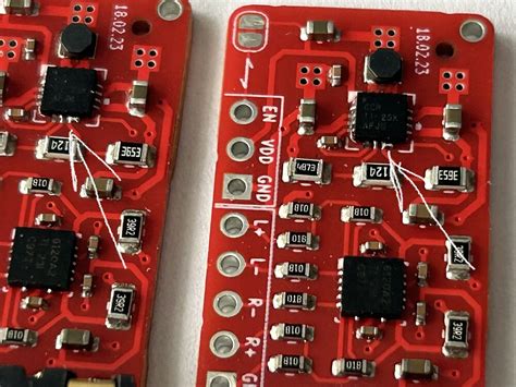
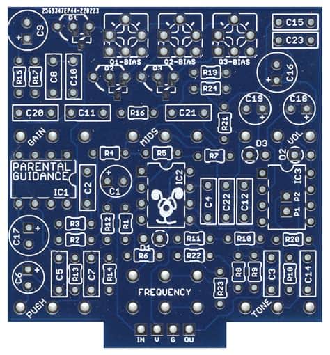
A PCB board blank, also known as a bare board or unpopulated board, is a printed circuit board without any electronic components soldered onto it. It consists of a non-conductive substrate, typically made from materials like FR-4 (a glass-reinforced epoxy laminate), with conductive copper traces and pads etched onto its surface. These copper traces and pads form the electrical connections between components that will be added later in the PCB assembly process.
Types of PCB Board Blanks
There are several types of PCB board blanks, each with their own unique characteristics and applications. Let’s explore some of the most common types:
Single-sided PCB Board Blanks
Single-sided PCB board blanks have copper traces and pads on only one side of the substrate. They are the simplest and most cost-effective type of PCB, making them ideal for low-complexity circuits and hobbyist projects. However, their limited routing options and lower component density make them less suitable for more advanced designs.
Double-sided PCB Board Blanks
Double-sided PCB board blanks feature copper traces and pads on both sides of the substrate, allowing for more complex routing and higher component density compared to single-sided boards. The two copper layers are connected using through-hole vias, which are small holes drilled through the board and plated with conductive material. Double-sided boards are widely used in a variety of electronic devices and offer a good balance between cost and functionality.
Multi-layer PCB Board Blanks
Multi-layer PCB board blanks consist of three or more conductive layers separated by insulating layers. The conductive layers are interconnected using through-hole or blind/buried vias. Multi-layer boards offer the highest Routing Density and complexity, making them suitable for advanced electronic systems, such as smartphones, computers, and aerospace applications. However, they are also the most expensive type of PCB board blank due to their complex manufacturing process.
Flexible PCB Board Blanks
Flexible PCB board blanks, also known as flex PCBs, are made from flexible materials like polyimide or polyester. They can bend and twist without damaging the copper traces, making them ideal for applications that require the PCB to conform to a specific shape or withstand repeated flexing, such as wearable electronics, medical devices, and automotive systems. Flex PCBs can be single-sided, double-sided, or multi-layer, depending on the design requirements.
Rigid-Flex PCB Board Blanks
Rigid-flex PCB board blanks combine the benefits of both rigid and flexible PCBs. They consist of one or more rigid PCB sections connected by flexible PCB sections, allowing for three-dimensional packaging and improved reliability in applications that require both stability and flexibility, such as aerospace, military, and industrial systems.
Here’s a table summarizing the different types of PCB board blanks:
| PCB Type | Layers | Complexity | Cost | Applications |
|---|---|---|---|---|
| Single-sided | 1 | Low | Low | Simple circuits, hobbyist projects |
| Double-sided | 2 | Medium | Medium | Most electronic devices |
| Multi-layer | 3+ | High | High | Advanced systems (smartphones, computers, aerospace) |
| Flexible | 1-3+ | Medium to High | Medium to High | Wearables, medical devices, automotive |
| Rigid-Flex | 1-3+ (rigid) + 1-2 (flex) | High | High | Aerospace, military, industrial |

PCB Board Blank Materials
The choice of material for a PCB board blank depends on several factors, including the intended application, operating environment, and required performance characteristics. Some common PCB substrate materials include:
FR-4
FR-4 is the most widely used PCB substrate material. It is a glass-reinforced epoxy laminate that offers good mechanical strength, thermal stability, and dielectric properties. FR-4 is suitable for a wide range of applications and is the standard material for most consumer electronics.
High-Tg FR-4
High-Tg FR-4 is a variant of standard FR-4 with improved thermal properties. It has a higher glass transition temperature (Tg), which makes it more resistant to thermal stress and suitable for applications that require higher operating temperatures, such as automotive and industrial electronics.
Polyimide
Polyimide is a high-performance polymer used in flexible PCBs and high-temperature applications. It offers excellent thermal stability, chemical resistance, and mechanical strength, making it ideal for demanding environments, such as aerospace and military systems.
Aluminum
Aluminum PCBs, also known as metal core PCBs (MCPCBs), use an aluminum substrate to enhance heat dissipation. They are commonly used in high-power LED lighting, power electronics, and other applications that generate significant amounts of heat.
Here’s a table comparing the properties of common PCB board blank materials:
| Material | Thermal Stability | Dielectric Constant | Loss Tangent | Applications |
|---|---|---|---|---|
| FR-4 | Good | 4.5 @ 1 MHz | 0.02 @ 1 MHz | General-purpose, consumer electronics |
| High-Tg FR-4 | Excellent | 4.5 @ 1 MHz | 0.02 @ 1 MHz | Automotive, industrial |
| Polyimide | Excellent | 3.5 @ 1 GHz | 0.002 @ 1 GHz | Flexible PCBs, aerospace, military |
| Aluminum | Excellent | – | – | High-power LEDs, power electronics |

PCB Design Considerations
Designing a PCB involves several key considerations to ensure optimal performance, manufacturability, and reliability. Some essential aspects to keep in mind when designing your PCB include:
Schematic Design
The first step in PCB design is creating a schematic diagram that represents the electrical connections between components. A well-designed schematic should be clear, organized, and follow best practices for component placement and labeling.
Component Placement
Proper component placement is crucial for PCB performance and manufacturability. Consider factors such as signal integrity, power distribution, thermal management, and mechanical constraints when placing components on your board.
Routing
PCB Routing involves creating the copper traces that connect components according to the schematic design. Ensure that your traces are properly sized for current carrying capacity, minimize signal crosstalk, and follow manufacturability guidelines, such as minimum trace width and spacing.
Ground and Power Planes
Incorporating ground and power planes in your PCB design helps to improve signal integrity, reduce electromagnetic interference (EMI), and distribute power effectively. Follow best practices for plane design, such as using appropriate plane splits and avoiding unnecessary slots or cutouts.
Design for Manufacturing (DFM)
Design your PCB with manufacturing considerations in mind to avoid potential issues during fabrication and assembly. This includes adhering to minimum feature sizes, providing adequate clearances, and following your manufacturer’s design rules and guidelines.

PCB Manufacturing Process
Once your PCB design is complete, it’s time to fabricate your board. The PCB manufacturing process typically involves the following steps:
- PCB Fabrication
- Substrate preparation
- Copper foil lamination
- Photoresist application and exposure
- Etching
- Soldermask and silkscreen application
- PCB Assembly
- Solder paste application
- Component placement
- Reflow soldering
- Inspection and testing
Frequently Asked Questions (FAQ)
1. What is the difference between a PCB board blank and a printed circuit board?
A PCB board blank is a bare board without any electronic components soldered onto it, while a printed circuit board (PCB) refers to the complete board assembly, including the substrate, copper traces, and soldered components.
2. Can I manufacture my own PCB board blanks at home?
While it is possible to create simple PCB board blanks at home using methods like toner transfer or chemical etching, it is generally recommended to use professional PCB fabrication services for higher-quality and more complex boards.
3. What is the most common PCB board blank material?
FR-4, a glass-reinforced epoxy laminate, is the most common PCB board blank material due to its good balance of mechanical, thermal, and electrical properties, as well as its cost-effectiveness.
4. How do I choose the right PCB board blank type for my project?
The choice of PCB board blank type depends on factors such as the complexity of your circuit, the required component density, the operating environment, and the budget. Consider the trade-offs between cost, performance, and manufacturability when selecting the appropriate board type for your project.
5. What are the key steps in designing a PCB?
The key steps in designing a PCB include creating a schematic diagram, placing components, routing traces, incorporating ground and power planes, and ensuring manufacturability. It’s essential to follow best practices and design guidelines to optimize your board’s performance and reliability.
Conclusion
PCB board blanks are the foundation of every electronic device, and understanding their types, materials, and design considerations is crucial for anyone interested in creating their own PCBs. By following the advice and guidance provided in this article, you’ll be well-prepared to design, manufacture, and assemble your own custom PCBs for a wide range of applications. Remember to always adhere to best practices, consult with experienced professionals when needed, and continuously learn and improve your skills in this fascinating field.

No responses yet