
What is Pad stack design?
Pad stack design refers to the process of defining the physical and electrical properties of the pads used to connect components to a printed circuit board (PCB). The pad stack includes the pad size, shape, drilling requirements, and layer stackup of the pads. Proper pad stack design is critical for ensuring reliable electrical connections, especially for fine pitch components with very small lead spacing.
Elements of a Pad Stack
A typical pad stack consists of the following elements:
- Pad size and shape
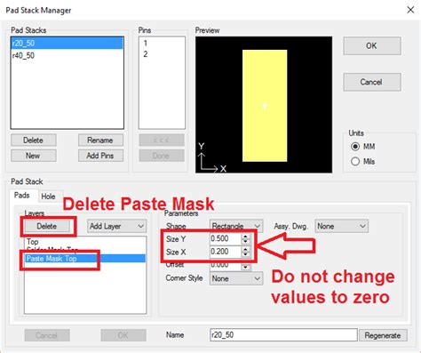
- Solder mask opening
- Drill hole size (for through-hole components)
- Conductive layers (copper)
- Insulating layers
The pad size and shape is designed based on the component package and pin pitch. Industry standards like IPC-7351 provide recommended pad geometries for different component types. The solder mask opening is typically larger than the copper pad to allow for solder wetting.
For through-hole components, the drill hole size is determined by the lead diameter plus an allowance for plating and assembly tolerance. The hole is plated with copper to electrically connect the top and bottom layers.
Importance of Proper Pad Stack Design
Improper pad stack design can lead to a variety of manufacturing and reliability issues, such as:
- Open or shorts due to insufficient solder joints
- Tombstoning of small chip components
- Solder bridging between fine pitch leads
- Breakout of pads during assembly or thermal cycling
Therefore, it is important to follow best practices and industry standards when designing pad stacks, especially for dense, fine pitch PCB designs.
Fine Pitch Components
Fine pitch components are electronic packages with a lead pitch (spacing between pins) of 0.5mm or less. Common examples include quad flat pack (QFP), ball grid array (BGA), and chip scale package (CSP) devices.
Challenges with Fine Pitch Components
As component pitches continue to shrink, designers face several challenges related to pad stack design and assembly:
-
Smaller pad sizes: Fine pitch components require smaller pads, which can be difficult to manufacture consistently. Smaller pads are also more prone to lifting or peeling.
-
Tighter tolerances: The margin for error in placement and soldering becomes smaller with fine pitch components. Slight misalignment can cause opens, shorts, or poor solder joints.
-
Solder bridging: With less space between leads, there is a higher risk of solder bridging (shorts) during reflow.
-
Inspection difficulties: Fine pitch solder joints are harder to inspect visually or with automated optical inspection (AOI) systems.
Design Techniques for Fine Pitch Components
To mitigate these challenges, PCB designers can employ several techniques:
-
Use solder mask defined (SMD) pads: SMD pads have a smaller copper area than the solder mask opening, which helps prevent solder bridging. The solder mask dams between pads also improve solder joint strength.
-
Optimize pad size and shape: Use industry standard pad geometries as a starting point, but simulate the solder joint formation to fine-tune the design. A well-balanced pad will promote self-centering of the component during reflow.
-
Increase copper weight: Heavier copper weights (1 oz or greater) provide more thermal mass to improve solderability and reduce pad lifting.
-
Use via-in-pad sparingly: While via-in-pad can be used to escape dense BGA patterns, it can also cause soldering issues if not done properly. Fill and planarize vias if possible.
-
Control solder volume: Too much solder can cause bridging, while too little can result in opens or weak joints. Use a stencil thickness that matches the component and pad size.
PCB Layer Stackup Considerations
The layer stackup of a PCB also plays a role in pad stack design, especially for fine pitch components with many pins.
Signal Layers
To escape from fine pitch BGA packs, it is often necessary to use blind and buried vias to access inner signal layers. This allows more routing channels to be used without increasing the overall layer count.
However, using too many signal layers can increase the cost and manufacturing complexity of the PCB. It is important to find a balance that meets both electrical and manufacturability requirements.
Power and Ground Layers
Placing power and ground planes adjacent to the outer layers helps improve signal integrity and provides shielding for sensitive signals. It also provides a low-impedance path for power delivery to fine pitch components.
When using via-in-pad for BGAs, it is important to have a solid reference plane beneath the pad to control the impedance of the via. Without a reference plane, the via can cause signal integrity issues.
Dielectric Thickness
The dielectric thickness between layers affects the impedance of traces and the mutual capacitance between pins. Thinner dielectrics allow for narrower traces and smaller vias, but also increase the risk of signal integrity issues.
For fine pitch components, it is important to use dielectric materials with good mechanical and thermal properties to prevent pad delamination or cracking.

Frequently Asked Questions
What is the smallest pad size that can be reliably manufactured?
– The minimum pad size depends on the PCB fabricator and their capabilities. In general, pads as small as 0.2mm can be manufactured, but 0.3-0.4mm is more common for fine pitch components. Consult with your fabricator for their specific limits.
How do you calculate the pad size for a given component pitch?
– IPC-7351 provides equations for calculating pad sizes based on component dimensions and assembly tolerances. However, these are just a starting point – the final pad size should be optimized through simulation and testing.
What is the difference between non-solder mask defined (NSMD) and solder mask defined (SMD) pads?
– NSMD pads have a copper area that extends beyond the solder mask opening, while SMD pads have a copper area that is smaller than the solder mask opening. SMD pads are preferred for fine pitch components because they help prevent solder bridging.
Can you use via-in-pad for fine pitch BGAs?
– Yes, via-in-pad can be used to escape from fine pitch BGAs, but it requires careful design and process control. The vias should be filled and planarized to prevent solder wicking, and a soldermask dam should be used to prevent solder from entering the via.
What are some common PCB assembly defects associated with fine pitch components?
– Some common defects include solder bridging (shorts), open solder joints, tombstoning of small chip components, and misalignment of leads. These defects can be minimized through proper pad stack design, stencil optimization, and process control.
Pad stack design is a critical aspect of PCB design, especially for fine pitch components. By following best practices and industry standards, designers can ensure reliable electrical connections and manufacturability. In Part 2 of this series, we will discuss advanced techniques for optimizing pad stacks and assembly processes for fine pitch components.
No responses yet