Types of PCB Soldering
Through-Hole Soldering
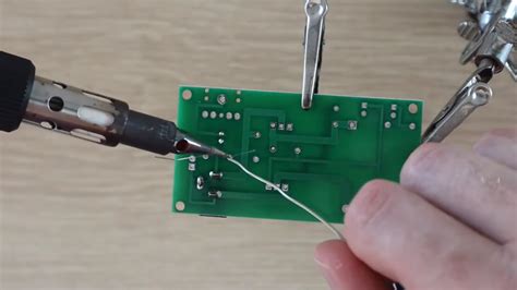
Through-hole soldering is a traditional method where component leads are inserted through drilled holes in the PCB and soldered on the opposite side. This technique is suitable for larger components and provides a strong mechanical connection.
Manual Soldering
Manual through-hole soldering involves using a soldering iron to heat the component lead and PCB pad simultaneously, allowing the solder to flow and form a joint. This method is ideal for low-volume production or prototyping.
Wave Soldering
Wave soldering is an automated process that involves passing the PCB over a molten solder wave. The component leads are pre-inserted into the PCB holes, and as the board moves over the wave, the solder adheres to the leads and pads, forming a connection. Wave soldering is suitable for high-volume production of through-hole PCBs.
Surface Mount Soldering
Surface Mount Technology (SMT) has become the predominant method for PCB Assembly due to its ability to accommodate smaller components and higher component density. In SMT soldering, components are placed directly on the PCB pads without the need for drilled holes.
Reflow Soldering
Reflow soldering is the most common SMT soldering technique. It involves applying solder paste (a mixture of solder particles and flux) to the PCB pads using a stencil or syringe. Components are then placed on the pasted pads, and the entire assembly is heated in a reflow oven. The solder paste melts and forms a connection between the component leads and pads.
Convection Reflow
Convection reflow ovens use hot air circulation to heat the PCB assembly evenly. The temperature profile is carefully controlled to ensure proper solder melting and cooling. Convection reflow is suitable for most SMT components and is widely used in the industry.
Infrared Reflow
Infrared (IR) reflow ovens use infrared radiation to heat the PCB assembly. IR energy is absorbed by the components and PCB, causing the solder paste to melt. IR reflow is faster than convection reflow but may not be suitable for all component types due to selective heating.
Vapor Phase Reflow
Vapor phase reflow uses a special fluid that vaporizes at a specific temperature. The PCB assembly is immersed in the vapor, which condenses on the surface, transferring heat uniformly to the solder paste. Vapor phase reflow provides excellent soldering quality but requires specialized equipment.
Hand Soldering
Hand soldering SMT components involves using a fine-tipped soldering iron to apply heat and solder to the component leads and pads. This method is suitable for rework, prototyping, or low-volume production.
Solder Materials
Leaded Solder
Traditionally, tin-lead (Sn-Pb) alloys were used for PCB soldering. Common compositions include 63Sn-37Pb (eutectic) and 60Sn-40Pb. Leaded solder has a lower melting point and provides good wetting properties, making it easier to work with.
Lead-Free Solder
Due to environmental and health concerns, lead-free solder alloys have become mandatory in many countries. Common lead-free alloys include:
- Tin-Silver-Copper (SAC): SAC alloys, such as SAC305 (96.5Sn-3.0Ag-0.5Cu), have higher melting points compared to leaded solder and require tighter process control.
- Tin-Copper (SnCu): SnCu alloys, like Sn99.3Cu0.7, are cost-effective alternatives but may result in slower wetting and duller joint appearance.
- Tin-Bismuth (SnBi): SnBi alloys, such as Sn42Bi58, have lower melting points and are used for low-temperature soldering applications.

Soldering Process Control
To ensure high-quality soldering, several factors must be controlled:
Temperature
Soldering temperature should be carefully regulated to ensure proper solder melting and to prevent component damage. The ideal temperature range depends on the solder alloy and component specifications.
Time
Soldering time should be long enough to allow proper solder wetting and joint formation but not so long as to cause component or PCB damage. Optimal soldering time varies based on the soldering method and component size.
Flux
Flux is a chemical agent that removes oxides from the metal surfaces and promotes solder wetting. Choosing the right flux type (e.g., rosin, water-soluble, no-clean) and applying it correctly is essential for achieving reliable solder joints.
Cleaning
After soldering, flux residues may need to be removed to prevent corrosion and improve the PCB’s aesthetic appearance. Cleaning methods include using solvents, aqueous solutions, or mechanical abrasion, depending on the flux type and PCB requirements.

Inspection and Quality Control
Post-soldering inspection is critical to identify defects and ensure the reliability of the soldered joints. Common inspection methods include:
- Visual Inspection: Manual or automated visual inspection checks for visible defects such as bridging, insufficient solder, or component misalignment.
- X-Ray Inspection: X-ray imaging allows for the detection of hidden solder joint defects, such as voids or cracks, in BGA or QFN packages.
- Automated Optical Inspection (AOI): AOI systems use cameras and image processing algorithms to detect surface-level soldering defects.
- Electrical Testing: In-circuit testing (ICT) or functional testing verifies the electrical continuity and functionality of the soldered connections.

Best Practices for PCB Soldering
To achieve optimal soldering results, consider the following best practices:
- Design for Manufacturability (DFM): Ensure that the PCB design incorporates proper pad sizes, component spacing, and thermal considerations for easy soldering.
- Use high-quality materials: Select reliable solder alloys, fluxes, and components from reputable suppliers.
- Control the environment: Maintain a clean and temperature-controlled soldering environment to minimize contamination and thermal issues.
- Follow manufacturer guidelines: Adhere to the recommended temperature profiles, soldering times, and handling procedures for specific components and PCBs.
- Provide adequate training: Ensure that soldering operators are well-trained in the selected soldering techniques and best practices.
- Implement process monitoring: Use statistical process control (SPC) techniques to monitor and maintain soldering process parameters within acceptable limits.
- Conduct regular maintenance: Regularly maintain and calibrate soldering equipment to ensure consistent performance.
Conclusion
PCB soldering is a critical process that directly impacts the quality and reliability of electronic devices. Understanding the various soldering techniques, materials, and best practices is essential for achieving optimal results. By selecting the appropriate soldering method, controlling process parameters, and implementing thorough inspection and quality control measures, manufacturers can produce high-quality PCBs that meet the demanding requirements of modern electronics.
Frequently Asked Questions (FAQ)
1. What is the difference between through-hole and surface mount soldering?
Through-hole soldering involves inserting component leads through drilled holes in the PCB and soldering them on the opposite side. Surface mount soldering, on the other hand, involves placing components directly on the PCB pads without the need for drilled holes. Surface mount soldering allows for smaller components and higher component density.
2. What are the advantages of lead-free solders?
Lead-free solders, such as tin-silver-copper (SAC) alloys, offer several advantages over traditional leaded solders. They are more environmentally friendly and comply with regulations that restrict the use of lead in electronics. Lead-free solders also provide better mechanical strength and resist thermal fatigue, enhancing the reliability of solder joints.
3. What is the purpose of flux in soldering?
Flux is a chemical agent used in soldering to remove oxides from the metal surfaces and promote solder wetting. It helps to ensure that the molten solder adheres properly to the component leads and PCB pads, resulting in a strong and reliable solder joint. Flux also helps to prevent oxidation during the soldering process.
4. How can I prevent solder bridging?
Solder bridging occurs when solder inadvertently connects adjacent pads or component leads. To prevent solder bridging, ensure that the PCB design has adequate spacing between pads and components. Use a fine-tipped soldering iron and apply the appropriate amount of solder. Avoid excessive heat and soldering time, which can cause the solder to spread uncontrollably.
5. What is the importance of post-soldering inspection?
Post-soldering inspection is crucial for identifying defects and ensuring the reliability of soldered joints. Visual inspection, automated optical inspection (AOI), X-ray inspection, and electrical testing are common methods used to detect soldering defects such as bridging, insufficient solder, component misalignment, or voids. Thorough inspection helps to catch and rectify issues before the PCB is integrated into the final product, reducing the risk of failures and improving overall quality.
| Soldering Technique | Advantages | Disadvantages |
|---|---|---|
| Through-Hole | – Strong mechanical connection – Suitable for larger components |
– Requires drilled holes – Limited component density |
| Surface Mount | – Higher component density – Smaller component sizes – Faster assembly |
– Requires precise component placement – More sensitive to thermal issues |
| Wave Soldering | – Automated process – High-volume production |
– Limited to through-hole components – Potential for bridging and shadowing |
| Reflow Soldering | – Automated process – Suitable for surface mount components |
– Requires solder paste application – Sensitive to temperature profiles |
| Hand Soldering | – Flexible and versatile – Suitable for rework and prototyping |
– Time-consuming – Operator skill dependent |
By understanding the strengths and limitations of each soldering technique, manufacturers can select the most appropriate method for their specific PCB assembly requirements, ensuring optimal quality and efficiency.
No responses yet