Introduction to Nixie Clocks
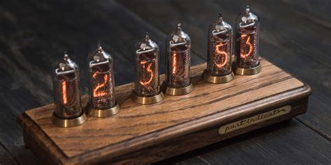
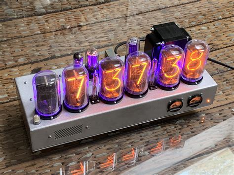
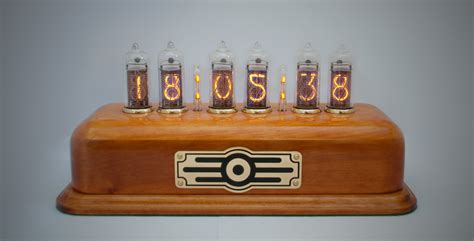
Nixie clocks are a unique and eye-catching way to display the time using vintage Nixie tubes. Nixie tubes were originally developed in the 1950s for electronic displays and were widely used in calculators, scientific instruments, and digital clocks until the 1970s when they were largely replaced by LED and LCD displays. In recent years, there has been renewed interest in Nixie tubes for their warm, retro glow and steampunk aesthetic appeal.
Building your own Nixie clock is a rewarding electronics project that combines the charm of vintage technology with modern microcontrollers and components. In this article, we’ll go through the steps to design and construct your own Nixie clock, including sourcing Nixie tubes, designing the power supply and driving circuitry, programming the microcontroller, and assembling it all into an attractive enclosure. Whether you’re an electronics enthusiast, a clock aficionado, or just appreciate the unique look of Nixie tubes, this project is sure to impress.
What You’ll Need
To build a Nixie clock, you’ll need the following key components:
| Component | Quantity |
|---|---|
| Nixie tubes | 4-6 (depending on desired format, e.g. HH:MM or HH:MM:SS) |
| High voltage power supply (150-180V DC) | 1 |
| Microcontroller (e.g. Arduino Nano) | 1 |
| Nixie tube driver ICs (e.g. 74141/K155ID1) | 4-6 (one per tube) |
| Resistors, capacitors, diodes | Various values |
| PCB (printed circuit board) | 1 |
| Enclosure | 1 |
| Buttons, switches | 2-3 |
| Wire, solder, tools | As needed |
Nixie Tubes
The heart of any Nixie clock are the Nixie tubes themselves. Nixie tubes come in a variety of sizes and styles, with the most common for clocks being the IN-14 (small), IN-8-2 (medium), and B-7971 (large). When sourcing Nixie tubes, look for ones in good condition with evenly lit digits and no damaged pins. Expect to pay anywhere from $10-50 per tube depending on rarity.
Power Supply
Nixie tubes require a high DC voltage, typically 150-180V, to ionize the neon/argon gas mixture and light up the digits. The current draw is low, around 2-3mA per tube. A common approach is to use a Boost Converter module to step up 12V DC to the required voltage. Alternatively, you can design a custom power supply using transformers and rectifier diodes.
Microcontroller
To keep time and multiplex the Nixie tube digits, a microcontroller is the brains of the Nixie clock. An Arduino Nano is a popular choice for its small size, low cost, and ease of use. The microcontroller keeps track of time using a real-time clock module or by counting milliseconds, and switches the cathodes of the Nixie tubes on and off in rapid succession.
Tube Drivers
Each Nixie tube cathode (0-9 digit) is switched using a high voltage transistor or dedicated Nixie driver IC chip. The classic driver is the 74141 BCD-to-decimal decoder which takes a 4-bit binary input and powers one of 10 output pins. The Russian K155ID1 is a pin-compatible driver still manufactured today. One driver is required per Nixie tube.
Other Components
Various resistors are needed to limit current to the tubes (10-30kΩ for the anodes, 15-100kΩ for cathodes) and other components. Capacitors are used for power supply filtering and debouncing buttons. Diodes protect against reverse voltage spikes. Buttons allow setting the time, while a power switch turns the clock on and off.
Circuit design
With the components selected, it’s time to design the circuit that will power and control the Nixie tubes. At a high level, the circuit consists of:
- Power supply (12V input stepped up to 180V)
- Microcontroller
- Nixie tube driver ICs
- Nixie tubes
- Anode resistors (10-30kΩ)
- Cathode resistors (15-100kΩ)
Here is a simplified block diagram:
12V DC -> Boost Converter -> 180V DC
                                |
                                v
                          Nixie Tubes
                                |
                                v
                       Anode Resistors
                                |
                                v
            Nixie Driver ICs (74141/K155ID1)
                                |
                                v
                         Microcontroller
                                |
                                v
            Buttons, Switches, other I/O
A more detailed schematic shows how the individual components are wired:
           180V
            |
            +-----------------+
            |                 |
            |            10kΩ |
            |                 |
            |                 |
            +-----------------+
            |     Nixie Tube  |
            +-----------------+
            |  a b c d  e f g |
            |  n n n n  n n n |
            |  o o o o  o o o |
            |  d d d d  d d d |
            |  e e e e  e e e |
            |  0 1 2 3  4 5 6 |
            +-----------------+
            |                 |
            |               __|__
            |              |     |
            |          15kΩ     100nF
            |              |     |
            |               -----
            |                 |
            +-----------------+
            |   Nixie Driver  |
            +-----------------+
            | A B C D   LE OE |
            | 1 1 1 1   1  1  |
            | 1 0 1 0   4  1  |
            | 4 8 4 8        4 |
            | 3 2 1 6   1   1 |
            +-----------------+
                     |
                     |
                     v
               Microcontroller
                     |
                     |
                     v
               Buttons, Switches
This is just one tube – the complete schematic has 4-6 tubes each with its own driver and anode/cathode resistors. The microcontroller connects to the driver ICs to set the digits. Buttons connect to the microcontroller inputs to allow setting the time.

PCB layout
With the circuit designed, the next step is to lay out the printed circuit board (PCB). A PCB makes wiring the components much easier compared to point-to-point soldering and allows for a compact, professional-looking design.
PCB Design software like KiCad or EAGLE lets you position the components and route the copper traces between pins. Some key considerations:
- Keep high voltage traces away from low voltage control logic
- Make power traces thicker to handle higher current
- Use large pads for tube pins for easier soldering
- Include mounting holes for securing PCB to enclosure
- Add silkscreen labels to indicate component placement and values
Here’s an example PCB layout for a 4-tube Nixie clock:
         +-------+  +-------+  +-------+  +-------+
     VCC |       |  |       |  |       |  |       | VCC
   +---->| Nixie |  | Nixie |  | Nixie |  | Nixie |<----+
   |     |  #1   |  |  #2   |  |  #3   |  |  #4   |     |
   |     +-------+  +-------+  +-------+  +-------+     |
   |         |          |          |          |         |
  GND        |          |          |          |        GND
   |      +------+   +------+   +------+   +------+     |
   +----->|Driver|   |Driver|   |Driver|   |Driver|<----+
          +------+   +------+   +------+   +------+
             |          |          |          |
             |          |          |          |
             v          v          v          v
          +-------------------------------------+
          |                                     |
          |            Arduino Nano             |
          |                                     |
          +-------------------------------------+
                  |     |     |     |     |
                  |     |     |     |     |
                  v     v     v     v     v
               +---+ +---+ +---+ +---+ +---+
               |Set| |   | |   | |   | |   |
               +---+ +---+ +---+ +---+ +---+
                      Buttons and Inputs
This layout has the Nixie tubes at the top, drivers in the middle, microcontroller at the bottom, and buttons along the edge. The high voltage is supplied at the top and kept away from the control logic at the bottom.
Firmware
With the hardware complete, the final piece is the firmware that runs on the microcontroller. The firmware is responsible for:
- Keeping track of time
- Multiplexing digits to the Nixie tubes
- Responding to button presses to set the time
Here’s a basic sketch in pseudocode:
// Initialize variables
currentTime = 00:00:00
buttonState = [0,0,0]
digit = [0,0,0,0,0,0]

// Setup
function setup() {
  // Set pin modes
  setPinModes()
  // Initialize RTC module
  initializeRTC()
}

// Main loop
function loop() {
  // Update current time
  currentTime = rtc.now()

  // Set digits from current time
  digit[0] = currentTime.hour / 10
  digit[1] = currentTime.hour % 10
  digit[2] = currentTime.minute / 10
  digit[3] = currentTime.minute % 10
  digit[4] = currentTime.second / 10
  digit[5] = currentTime.second % 10

  // Check button states
  for i = 0 to 3
    buttonState[i] = digitalRead(buttonPin[i])
    if buttonState[i] == HIGH then
      updateTime()

  // Multiplex digits to tubes
  for i = 0 to 5
    setDigit(i, digit[i])
    delay(2)
    clearDigit(i)
}

function setDigit(index, value)
  // Set driver IC pins for digit value
  digitalWrite(driver[index].A, value & 1)
  digitalWrite(driver[index].B, value & 2)
  digitalWrite(driver[index].C, value & 4)
  digitalWrite(driver[index].D, value & 8)
  // Disable output
  digitalWrite(driver[index].LE, LOW)
  // Enable output
  digitalWrite(driver[index].OE, LOW)

function clearDigit(index)
  // Disable output
  digitalWrite(driver[index].OE, HIGH)
This gives you a basic idea of how the code works. The microcontroller keeps track of the current time using an RTC module or its internal clock. It breaks this down into digits for each tube. In a fast loop, it sets the driver IC input pins to the corresponding digit value, enables the output to light up the digit, then disables the output and moves to the next digit. Buttons are checked each cycle to see if the time needs to be updated.
Of course, a complete sketch would include additional functions for setting the time from button presses, configuring the RTC module, and so on. But this outlines the core functionality for displaying the time on the Nixie tubes.
Assembling the Clock
With the PCB fabricated and components sourced, it’s time to put it all together. The general assembly process is:
- Solder resistors, capacitors, diodes and small components
- Solder microcontroller and driver ICs (use sockets for easy replacement)
- Solder tube sockets to the PCB
- Insert Nixie tubes into sockets
- Wire up power supply and buttons
- Program microcontroller with firmware
- Test each digit and debug any issues
- Install assembled PCB in enclosure
- Apply finishing touches (paint, stain, decals)
Take your time with the soldering and double-check all connections before powering on for the first time. Making a mistake with the high voltage can damage components.
For the enclosure, you can repurpose an existing clock case, build a custom one from wood, metal or 3D-printed plastic, or simply mount the PCB on a base. The key is to securely fasten the PCB while still allowing access to the tubes and buttons.
Frequently Asked Questions
What if a Nixie tube breaks or burns out?
Nixie tubes are relatively robust but they can break if dropped and may burn out after a few years of continuous use. Replacing a tube is simply a matter of swapping in a new one. You may need to adjust the anode resistor value if using a different type of tube.
Can I use a different microcontroller besides Arduino?
Certainly, any microcontroller with enough digital I/O pins to drive the Nixie tubes can be used. Popular alternatives include Raspberry Pi Pico, ESP8266/ESP32, Teensy, and even bare ATmega chips. You’ll need to port the Arduino code to the appropriate language (e.g. MicroPython, C++).
How do I add extra features like alarms, temperature, date?
Once you have the basic Nixie clock working, you can extend its functionality with additional features. Some ideas:
- Display date (MM.DD/DD.MM) or seconds
- Set multiple alarms with snooze
- Automatically dim tubes at night
- Show temperature and humidity
- Integrate GPS or radio time sync
- Add Bluetooth or WiFi control from smartphone
You’ll need to modify the hardware (e.g. add sensors, wireless modules) and firmware to support the extra features. There are many open-source designs to reference for inspiration.
How much does it cost to build a Nixie clock?
The cost mainly depends on the price and quantity of Nixie tubes. The electronics components (microcontroller, PCB, resistors, etc.) are relatively inexpensive at under $50 total. But a set of 6 Nixie tubes can cost anywhere from $50-300 depending on size, rarity, and condition. Add in another $20-50 for the enclosure. So all-in expect to spend at least $150-400+ to build a Nixie clock from scratch.
What safety precautions should I take?
Nixie clocks use high voltage around 150-200V DC which can give you a nasty shock if you’re not careful. Always unplug the power before working on the clock. Discharge any capacitors before handling the PCB. Use insulated tools and take care not to touch exposed leads. Keep the high voltage area covered in the finished clock to prevent accidental contact.
Conclusion
Building your own Nixie clock is a challenging yet rewarding project that combines the best of vintage and modern electronics. From sourcing the Nixie tubes to designing the circuit, laying out the PCB, coding the firmware, and assembling it all in a custom enclosure, there are many opportunities to learn and express your creativity.
While Nixie clocks may not be as practical as modern digital clocks, they more than make up for it with their unique retro charm and warm, mesmerizing glow. A Nixie clock makes a great conversation piece on your desk or nightstand and is sure to impress guests with your electronics prowess.
We’ve covered the basics of how Nixie clocks work and how to build one from scratch. But there’s much more to explore in the world of Nixie tubes and other vintage displays. With some imagination and tinkering, you can create your own one-of-a-kind timepiece that blends art, science, and history.
So grab some Nixie tubes, warm up your soldering iron, and enjoy the journey of building your own Nixie clock. Happy tinkering!
No responses yet