Introduction to Boost Converters
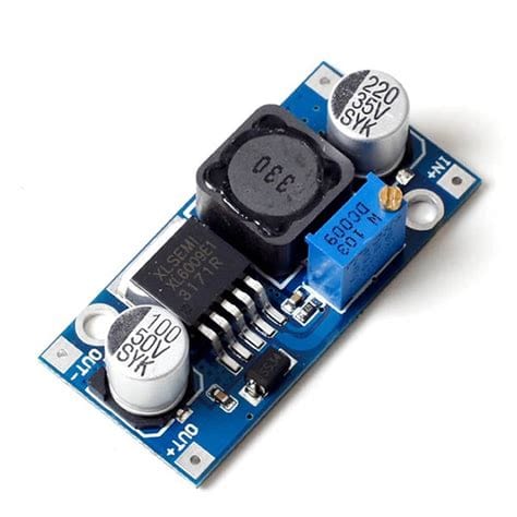
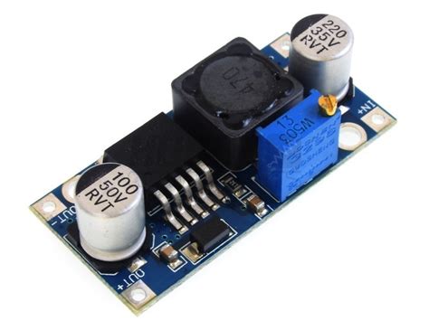
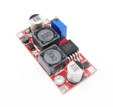
A boost converter, also known as a step-up converter, is a DC-to-DC power converter that increases the voltage from its input to its output. It is a class of switched-mode power supply (SMPS) containing at least two semiconductors (a diode and a transistor) and at least one energy storage element, either a capacitor, inductor, or the two in combination. Filters made of capacitors are normally added to the output of the converter to reduce output voltage ripple and the inductor connected in series of the input DC source in order to reduce the current ripple.
Key Components of a Boost Converter
The key components of a boost converter are:
- Inductor: The inductor is the main energy storage element. It stores energy in the form of a magnetic field when current flows through it.
- Switch: The switch, usually a MOSFET or IGBT, is used to control the inductor’s charging and discharging cycles.
- Diode: The diode prevents current from flowing back into the switch during the discharge cycle.
- Capacitor: The capacitor reduces voltage ripple and maintains a constant output voltage.
- PWM Controller: The PWM (Pulse Width Modulation) controller regulates the duty cycle of the switch to control the output voltage.
How Does a Boost Converter Work?
The basic principle of a boost converter consists of two distinct states:
State 1: Charging the Inductor (Switch Closed)
When the switch is closed, current flows through the inductor in a clockwise direction, and the inductor stores energy by generating a magnetic field. The polarity of the left side of the inductor is positive.
State 2: Discharging the Inductor (Switch Open)
When the switch is opened, the current will be reduced as the impedance is higher. The magnetic field previously created will be destroyed to maintain the current flow towards the load. Thus the polarity will be reversed (meaning the left side of inductor will be negative now). As a result, two sources will be in series causing a higher voltage to charge the capacitor through the diode.

Boost Converter Operating Modes
Boost converters can operate in two different modes:
Continuous Conduction Mode (CCM)
In continuous conduction mode, the current through the inductor never falls to zero. This results in higher efficiency but requires a larger inductor value.
Discontinuous Conduction Mode (DCM)
In discontinuous conduction mode, the current through the inductor falls to zero for a portion of the switching period. This mode is less efficient but allows for smaller inductor values.

Boost Converter Design Considerations
When designing a boost converter, several factors must be considered:
- Input and Output Voltage: The input and desired output voltage will determine the duty cycle and the stress on the components.
- Power Rating: The power rating will determine the current handling requirements of the components.
- Inductor Value: The inductor value affects the ripple current, efficiency, and operating mode (CCM or DCM).
- Capacitor Value: The capacitor value affects the output voltage ripple and transient response.
- Switching Frequency: Higher switching frequencies allow for smaller component sizes but also increase switching losses.

Boost Converter Applications
Boost converters are used in a wide variety of applications, such as:
- Power Supplies: Boost converters are often used in power supplies to step up the input voltage to the desired output voltage.
- Battery-Powered Devices: In battery-powered devices, boost converters can be used to maintain a constant voltage as the battery discharges.
- Solar Power Systems: Boost converters are used in solar power systems to step up the voltage from the solar panels to the required level for the inverter or battery system.
- Automotive Electronics: In automotive systems, boost converters are used to step up the vehicle’s 12V battery voltage to the higher voltages required by certain electronic components.
Boost Converter Efficiency
The efficiency of a boost converter is determined by several factors, including:
- Component Losses: The resistance of the inductor and the forward voltage drop of the diode contribute to power losses.
- Switching Losses: The power dissipated during the switching transitions of the MOSFET or IGBT.
- Operating Mode: Continuous conduction mode (CCM) generally offers higher efficiency than discontinuous conduction mode (DCM).
- Inductor and Capacitor Selection: Choosing components with low equivalent series resistance (ESR) helps to minimize power losses.
Calculating Boost Converter Efficiency
Boost converter efficiency can be calculated using the following formula:
Efficiency (η) = (Output Power / Input Power) × 100%
Where:
– Output Power = Output Voltage × Output Current
– Input Power = Input Voltage × Input Current
Boost Converter Topology Variations
There are several variations of the basic boost converter topology, each with its own advantages and applications:
Interleaved Boost Converter
An interleaved boost converter uses multiple parallel boost converters with their switching cycles phase-shifted to reduce input and output current ripple and improve efficiency.
Three-Level Boost Converter
A three-level boost converter uses an additional capacitor and two additional switches to achieve higher voltage gain and reduced voltage stress on the components.
Quadratic Boost Converter
A quadratic boost converter uses two inductors and two switches to achieve higher voltage gain than a traditional boost converter.
Boost Converter Control Methods
There are two main control methods for boost converters:
Voltage Mode Control
In voltage mode control, the output voltage is compared to a reference voltage, and the error signal is used to control the duty cycle of the switch.
Current Mode Control
In current mode control, the inductor current is measured and compared to a reference current, and the error signal is used to control the duty cycle of the switch. This method provides better line regulation and faster transient response.
Boost Converter Design Example
Let’s design a boost converter with the following specifications:
- Input Voltage: 12V
- Output Voltage: 24V
- Output Power: 50W
- Switching Frequency: 100kHz
Step 1: Calculate the Duty Cycle
Duty Cycle (D) = 1 – (Input Voltage / Output Voltage) = 1 – (12V / 24V) = 0.5 or 50%
Step 2: Calculate the Inductor Value
Assuming a ripple current of 20% of the average input current:
L = (Input Voltage × (1 – D)) / (Ripple Current × Switching Frequency)
L = (12V × (1 – 0.5)) / (0.833A × 100kHz) = 72µH
Step 3: Calculate the Capacitor Value
Assuming an output voltage ripple of 1%:
C = (Output Current × D) / (Output Voltage Ripple × Switching Frequency)
C = (2.083A × 0.5) / (0.24V × 100kHz) = 21.7µF
Step 4: Select the MOSFET and Diode
The MOSFET and diode should be selected based on their voltage and current ratings, as well as their switching characteristics.
Frequently Asked Questions (FAQ)
1. What is the difference between a boost converter and a buck converter?
A boost converter steps up the input voltage to a higher output voltage, while a buck converter steps down the input voltage to a lower output voltage.
2. Can a boost converter be used to step down voltage?
No, a boost converter can only step up voltage. To step down voltage, a buck converter or a Buck-Boost converter should be used.
3. What is the maximum voltage gain of a boost converter?
Theoretically, the voltage gain of a boost converter is infinite. However, in practice, the voltage gain is limited by the inductor and capacitor sizes, as well as the switch and diode ratings.
4. How do I choose the appropriate inductor and capacitor values for a boost converter?
The inductor and capacitor values are chosen based on the desired input and output voltages, the output power, the switching frequency, and the acceptable ripple currents and voltages.
5. What are the advantages of using an interleaved boost converter?
An interleaved boost converter offers reduced input and output current ripple, improved efficiency, and better heat distribution compared to a single boost converter.
Conclusion
Boost converters are essential power conversion devices that step up DC voltage from a lower level to a higher level. They are widely used in various applications, from power supplies and battery-powered devices to solar power systems and automotive electronics. By understanding the working principles, design considerations, and control methods of boost converters, engineers can design efficient and reliable power conversion systems to meet the ever-growing demands of modern electronic devices.

No responses yet