Introduction to AutoCAD and Gerber files
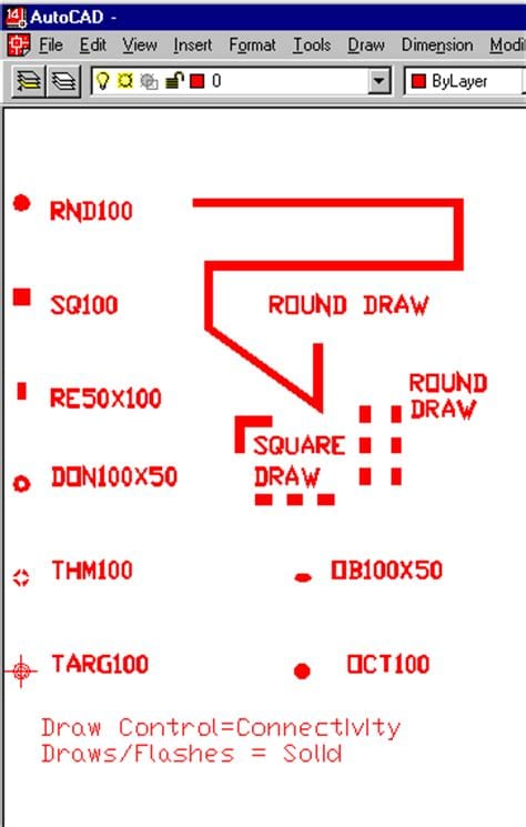
AutoCAD is a popular computer-aided design (CAD) software used by engineers, architects, and designers to create precise 2D and 3D drawings. It is widely used in various industries, including electronics, for designing printed circuit boards (PCBs). To manufacture PCBs, the design created in AutoCAD needs to be converted into a format that can be understood by PCB fabrication machines. This is where Gerber files come into play.
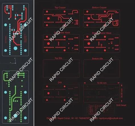
Gerber files, also known as Gerber format or RS-274X format, are a standard file format used in the PCB industry for describing the layout of a PCB. They contain information about the copper layers, solder mask, silkscreen, and drill holes of a PCB. Gerber files are essential for PCB fabrication as they provide the necessary data for the manufacturing process.
In this article, we will guide you through the process of generating Gerber files from your AutoCAD designs, ensuring that your PCBs can be accurately manufactured.
Prerequisites
Before we dive into the process of generating Gerber files from AutoCAD, make sure you have the following:
- AutoCAD Software installed on your computer
- A completed PCB Design in AutoCAD
- A basic understanding of PCB layers and their purposes
Step-by-step guide to generate Gerber files from AutoCAD
Step 1: Prepare your PCB design in AutoCAD
- Open your PCB design in AutoCAD.
- Ensure that your design is complete and all layers are properly defined.
- Check for any errors or inconsistencies in your design, such as overlapping traces or missing connections.
Step 2: Set up the plot configuration
- Click on the “Output” tab in the AutoCAD ribbon.
- In the “Plot” panel, click on the “Plot” button to open the “Plot” dialog box.
- In the “Printer/plotter” section, select “None” from the drop-down menu.
- In the “Plot to file” section, check the box next to “Plot to file” and choose a location to save your Gerber files.
- In the “Plot style table” section, select “Monochrome.ctb” from the drop-down menu.
- In the “Plot area” section, choose “Window” and select the area of your PCB design that you want to plot.
- In the “Plot scale” section, set the scale to 1:1.
- In the “Plot offset” section, set both X and Y values to 0.
Step 3: Configure the plot settings for each layer
- In the “Plot” dialog box, click on the “Edit Plot Configuration” button.
- In the “Plot Configuration Editor” dialog box, you will see a list of your PCB layers.
- For each layer that you want to include in your Gerber files, follow these steps:
a. Select the layer from the list.
b. In the “Plot” column, check the box to include the layer in the plot.
c. In the “Plot style” column, select “Monochrome.ctb” from the drop-down menu.
d. In the “Lineweight” column, select “0.00mm” from the drop-down menu.
e. In the “Color” column, select “Black” from the drop-down menu. - After configuring the plot settings for each layer, click “OK” to close the “Plot Configuration Editor” dialog box.
Step 4: Generate the Gerber files
- Back in the “Plot” dialog box, click on the “OK” button to start the plotting process.
- AutoCAD will generate a separate Gerber file for each layer you selected in the plot configuration.
- The Gerber files will be saved in the location you specified earlier.

Tips for creating high-quality Gerber files
- Use a consistent naming convention for your PCB layers to avoid confusion.
- Ensure that your design follows the PCB manufacturer’s design guidelines, such as minimum trace width and spacing.
- Perform a design rule check (DRC) in AutoCAD to identify and resolve any design issues before generating Gerber files.
- Include all necessary layers in your Gerber files, such as copper layers, solder mask, silkscreen, and drill files.
- Verify the generated Gerber files using a Gerber viewer to ensure that they accurately represent your PCB design.
Common issues and troubleshooting
Issue 1: Gerber files are not generated
If AutoCAD fails to generate Gerber files, check the following:
- Ensure that you have selected the correct printer/plotter and plot to file option in the plot configuration.
- Verify that you have selected the desired layers to be included in the plot.
- Check if there are any issues with your PCB design, such as missing or corrupt objects.
Issue 2: Gerber files are incorrect or incomplete
If the generated Gerber files do not accurately represent your PCB design, consider the following:
- Double-check your plot configuration settings, including the plot scale and offset.
- Ensure that you have selected the appropriate plot style and lineweight for each layer.
- Verify that all necessary layers are included in the plot.
Issue 3: PCB manufacturer rejects the Gerber files
If your PCB manufacturer rejects the Gerber files you provided, it may be due to the following reasons:
- The Gerber files do not follow the manufacturer’s design guidelines.
- There are missing or incorrect layers in the Gerber files.
- The Gerber files contain design errors or inconsistencies.
To resolve these issues, consult with your PCB manufacturer and make the necessary adjustments to your design and Gerber files.
Best practices for PCB design in AutoCAD
To ensure that your PCB design can be easily converted into high-quality Gerber files, follow these best practices:
- Use a consistent grid size and snap settings to maintain accuracy and precision in your design.
- Create a separate layer for each component of your PCB, such as copper layers, solder mask, and silkscreen.
- Follow the PCB manufacturer’s design guidelines for minimum trace width, spacing, and drill hole size.
- Use clear and concise naming conventions for your layers and objects.
- Perform regular design rule checks to identify and resolve any design issues early in the process.
By adhering to these best practices, you can streamline the process of generating Gerber files and ensure that your PCB design is ready for manufacturing.
Frequently Asked Questions (FAQ)
- What is the difference between AutoCAD and Gerber files?
-
AutoCAD is a CAD software used for designing PCBs, while Gerber files are a standard file format used for describing the layout of a PCB for manufacturing purposes.
-
Can I generate Gerber files from AutoCAD without using the plot configuration?
-
No, the plot configuration is essential for generating Gerber files from AutoCAD, as it allows you to set up the necessary parameters for each layer of your PCB design.
-
What should I do if my PCB manufacturer rejects my Gerber files?
-
If your PCB manufacturer rejects your Gerber files, consult with them to identify the specific issues and make the necessary adjustments to your design and Gerber files accordingly.
-
How can I ensure that my PCB design is compatible with the manufacturing process?
-
To ensure compatibility, follow the PCB manufacturer’s design guidelines, perform regular design rule checks, and verify your Gerber files using a Gerber viewer before submitting them for manufacturing.
-
Can I include multiple PCB designs in a single set of Gerber files?
- No, each PCB design should have its own set of Gerber files to avoid confusion and ensure accurate manufacturing.
Conclusion
Generating Gerber files from your AutoCAD PCB designs is a crucial step in the PCB manufacturing process. By following the step-by-step guide and best practices outlined in this article, you can create high-quality Gerber files that accurately represent your PCB design. Remember to prepare your design carefully, configure your plot settings correctly, and verify your Gerber files before submitting them to your PCB manufacturer. By doing so, you can ensure that your PCBs are manufactured according to your specifications and meet the highest quality standards.
No responses yet