Introduction to Flexible-Rigid PCBs
Flexible-Rigid PCBs, also known as Rigid-flex PCBs, are a unique combination of flexible and rigid printed circuit boards. They offer the best of both worlds by providing the flexibility and durability of flexible PCBs along with the stability and reliability of rigid PCBs. This innovative technology has revolutionized the electronics industry, enabling the creation of compact, lightweight, and highly reliable electronic devices.
What are Flexible-Rigid PCBs?
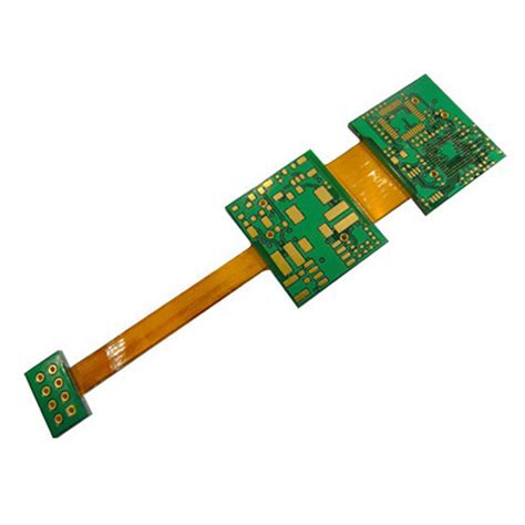
A Flexible-Rigid PCB is a hybrid printed circuit board that consists of both flexible and rigid substrates. The flexible portions are typically made of polyimide or other flexible materials, while the rigid portions are made of standard FR-4 or other rigid materials. The flexible and rigid sections are interconnected using various methods, such as plated through-holes (PTHs), blind vias, or buried vias.
Advantages of Flexible-Rigid PCBs
Flexible-Rigid PCBs offer several advantages over traditional rigid PCBs, including:
- Space savings: Flexible-Rigid PCBs allow for more compact and lightweight designs, as the flexible portions can be folded or bent to fit into tight spaces.
- Improved reliability: The combination of flexible and rigid substrates reduces stress on components and connections, resulting in improved reliability and longer product life.
- Enhanced signal integrity: Flexible-Rigid PCBs minimize the need for connectors and cables, reducing signal loss and improving overall signal integrity.
- Cost-effectiveness: By reducing the number of connectors and cables required, Flexible-Rigid PCBs can lower overall manufacturing and assembly costs.
Designing Flexible-Rigid PCBs
Key Considerations
When designing Flexible-Rigid PCBs, several key factors must be considered to ensure optimal performance and reliability:
- Material selection: Choose appropriate flexible and rigid substrate materials based on the application’s requirements, such as temperature range, flexibility, and durability.
- Bend radius: Determine the minimum bend radius for the flexible portions to avoid excessive stress on the materials and components.
- Layer stackup: Design the layer stackup to optimize signal integrity, power distribution, and mechanical stability.
- Component placement: Carefully place components to minimize stress during flexing and to ensure proper clearances for assembly and operation.
Best Practices
To achieve the best results when designing Flexible-Rigid PCBs, follow these best practices:
- Use curved traces instead of sharp angles to reduce stress concentration points.
- Provide sufficient clearance around components and vias to accommodate flexing.
- Use strain relief features, such as stiffeners or adhesives, to minimize stress on critical areas.
- Incorporate teardrops at the junction of traces and pads to improve structural integrity.
- Follow the manufacturer’s guidelines for material selection, layer stackup, and design rules.

Assembling Flexible-Rigid PCBs
Challenges and Solutions
Assembling Flexible-Rigid PCBs can be more challenging than assembling traditional rigid PCBs due to the unique characteristics of the flexible portions. Some common challenges and their solutions include:
- Handling: Use specialized fixtures and tools to support and protect the flexible portions during assembly.
- Soldering: Employ low-temperature soldering techniques, such as vapor phase or laser soldering, to minimize thermal stress on the flexible substrates.
- Strain relief: Incorporate strain relief features, such as adhesives or mechanical supports, to prevent damage to components and connections during flexing.
- Inspection: Use advanced inspection techniques, such as 3D X-ray or micro-CT scanning, to verify the integrity of internal connections and structures.
Assembly Process Overview
The assembly process for Flexible-Rigid PCBs typically involves the following steps:
- Solder paste application: Apply solder paste to the component pads using a stencil or dispensing system.
- Component placement: Place components onto the PCB using a pick-and-place machine or manual methods.
- Reflow soldering: Perform reflow soldering to form strong and reliable solder joints between the components and the PCB.
- Cleaning: Remove any flux residue or contaminants using appropriate cleaning methods, such as ultrasonic or spray cleaning.
- Inspection: Conduct visual and automated inspection to ensure proper component placement, solder joint quality, and overall assembly integrity.
- Final assembly: Perform any additional assembly steps, such as attaching connectors, mounting hardware, or enclosures.

Testing and Quality Assurance
Electrical Testing
Electrical testing is crucial to ensure that the assembled Flexible-Rigid PCB functions as intended. Common electrical tests include:
- Continuity test: Verify that all intended connections are present and there are no short circuits.
- Insulation resistance test: Measure the resistance between isolated conductors to ensure adequate insulation.
- Functional test: Perform a comprehensive test of the PCB’s functionality under various operating conditions.
Mechanical Testing
Mechanical testing is necessary to validate the Flexible-Rigid PCB’s ability to withstand the intended mechanical stresses and strains. Typical mechanical tests include:
- Bend test: Evaluate the PCB’s ability to withstand repeated bending cycles without damage or degradation.
- Twist test: Assess the PCB’s resistance to twisting forces that may occur during assembly or operation.
- Shock and vibration test: Verify the PCB’s ability to withstand the expected levels of shock and vibration in its intended application.
Reliability Testing
Reliability testing is essential to ensure that the Flexible-Rigid PCB will perform reliably over its expected lifetime. Common reliability tests include:
- Thermal cycling: Expose the PCB to alternating high and low temperatures to simulate thermal stresses encountered during operation.
- Humidity testing: Evaluate the PCB’s resistance to moisture and humidity-related failures.
- Accelerated life testing: Perform tests under elevated stress conditions to predict the PCB’s long-term reliability.
| Test Category | Purpose | Common Tests |
|---|---|---|
| Electrical | Verify functionality and connectivity | Continuity, insulation resistance, functional |
| Mechanical | Assess mechanical durability | Bend, twist, shock and vibration |
| Reliability | Predict long-term performance | Thermal cycling, humidity, accelerated life |

Case Studies and Applications
Wearable Electronics
Flexible-Rigid PCBs are ideal for wearable electronics applications, where the ability to conform to the human body is essential. Examples include:
- Smartwatches: Flexible-Rigid PCBs enable compact and lightweight designs that can wrap around the wrist.
- Fitness trackers: The flexible portions allow the device to adapt to the user’s movements and maintain skin contact for accurate sensor readings.
- Medical monitoring devices: Flexible-Rigid PCBs enable comfortable and discreet placement of sensors for continuous health monitoring.
Automotive Electronics
In the automotive industry, Flexible-Rigid PCBs are used to create compact and reliable electronic modules that can withstand harsh environmental conditions. Applications include:
- Instrument clusters: Flexible-Rigid PCBs allow for thin and curved displays that integrate seamlessly with the vehicle’s interior.
- Sensors and control modules: The flexible portions enable the placement of electronics in tight spaces and reduce the need for connectors and cables.
- Infotainment systems: Flexible-Rigid PCBs support the integration of multiple functions, such as audio, video, and navigation, into a single compact module.
Aerospace and Defense
Flexible-Rigid PCBs are well-suited for aerospace and defense applications, where high reliability and durability are critical. Examples include:
- Avionics: Flexible-Rigid PCBs enable the creation of compact and lightweight electronic modules that can withstand extreme temperatures, vibration, and shock.
- Missile guidance systems: The flexible portions allow for the integration of electronics into the limited space available in missile bodies.
- Satellite communication devices: Flexible-Rigid PCBs support the creation of high-density, multi-functional modules that can operate reliably in the harsh environment of space.
FAQ
-
What is the difference between a Flexible-Rigid PCB and a traditional rigid PCB?
A Flexible-Rigid PCB combines both flexible and rigid substrates, allowing for greater design flexibility and improved reliability compared to traditional rigid PCBs. The flexible portions enable the PCB to be folded or bent to fit into tight spaces, while the rigid portions provide structural support and stability. -
What are the key benefits of using Flexible-Rigid PCBs?
The key benefits of using Flexible-Rigid PCBs include space savings, improved reliability, enhanced signal integrity, and cost-effectiveness. By reducing the need for connectors and cables, Flexible-Rigid PCBs enable more compact and lightweight designs, while also minimizing signal loss and improving overall system reliability. -
What are some common applications for Flexible-Rigid PCBs?
Flexible-Rigid PCBs are commonly used in various applications, including wearable electronics, automotive electronics, aerospace and defense systems, and medical devices. They are particularly well-suited for applications that require compact, lightweight, and highly reliable electronic assemblies that can withstand harsh environmental conditions. -
What are the main challenges in assembling Flexible-Rigid PCBs?
The main challenges in assembling Flexible-Rigid PCBs include handling the flexible portions without damage, soldering components without causing thermal stress to the flexible substrates, providing adequate strain relief to prevent damage during flexing, and inspecting the internal connections and structures to ensure assembly integrity. -
How can the reliability of Flexible-Rigid PCBs be ensured?
The reliability of Flexible-Rigid PCBs can be ensured through a combination of careful design, appropriate material selection, advanced assembly techniques, and thorough testing. Key steps include choosing suitable flexible and rigid substrate materials, incorporating strain relief features, using low-temperature soldering methods, and conducting comprehensive electrical, mechanical, and reliability testing.
Conclusion
Flexible-Rigid PCBs offer a powerful solution for creating compact, lightweight, and highly reliable electronic assemblies. By combining the benefits of flexible and rigid substrates, Flexible-Rigid PCBs enable designers to overcome the limitations of traditional rigid PCBs and create innovative products that meet the demands of today’s markets.
To successfully implement Flexible-Rigid PCBs, it is essential to follow best practices in design, assembly, and testing. By carefully considering material selection, bend radius, layer stackup, and component placement, designers can create Flexible-Rigid PCBs that are optimized for performance and reliability. Advanced assembly techniques, such as low-temperature soldering and strain relief features, ensure that the assembled PCBs can withstand the intended mechanical stresses and strains. Comprehensive electrical, mechanical, and reliability testing validates the PCB’s functionality, durability, and long-term performance.
As the demand for compact, lightweight, and reliable electronic devices continues to grow, Flexible-Rigid PCBs will play an increasingly important role in enabling the next generation of innovative products. By understanding the key considerations and best practices associated with Flexible-Rigid PCBs, designers and manufacturers can unlock the full potential of this powerful technology and create electronic assemblies that are simpler, more reliable, and better suited to the needs of their customers.
No responses yet