Introduction to DC Motors
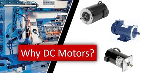
DC motors are widely used in various applications due to their simplicity, reliability, and ease of control. They convert electrical energy into mechanical energy, allowing you to power anything from small toys to industrial machinery. When designing circuits to drive DC motors, it’s important to consider factors such as motor specifications, power requirements, and control methods. In this article, we’ll explore how to drive small DC motors using Altium Designer, a powerful PCB design software.
Types of DC Motors
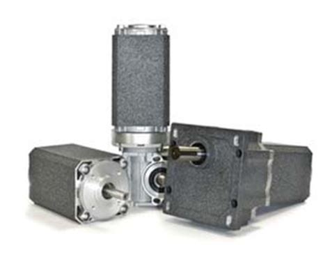
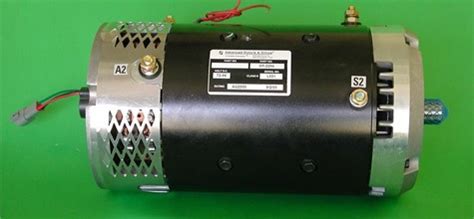
There are several types of DC motors, each with its own characteristics and applications:
| Motor Type | Description | Applications |
|---|---|---|
| Brushed DC Motors | Simple construction, easy to control | Toys, small appliances, automotive |
| Brushless DC Motors | High efficiency, low maintenance | Drones, electric vehicles, industrial automation |
| Stepper Motors | Precise positioning, high torque | 3D printers, CNC machines, robotics |
| Servo Motors | Accurate position control | Robotics, RC vehicles, industrial automation |
Motor Specifications
When selecting a DC motor for your project, consider the following specifications:
- Voltage rating: The nominal voltage required to operate the motor
- Current rating: The maximum current the motor can draw under load
- Power rating: The mechanical power output of the motor
- Speed: The rotational speed of the motor, usually expressed in RPM (revolutions per minute)
- Torque: The rotational force produced by the motor
Designing Motor Driver Circuits
To control a DC motor, you need a motor driver circuit that can provide the necessary power and control signals. The driver circuit acts as an interface between your microcontroller or control logic and the motor itself.
H-Bridge
An H-bridge is a commonly used motor driver circuit that allows you to control the direction and speed of a DC motor. It consists of four switching elements (usually MOSFETs or BJTs) arranged in an H configuration.
The basic operation of an H-bridge is as follows:
- To rotate the motor in one direction, turn on switches Q1 and Q4 while keeping Q2 and Q3 off.
- To rotate the motor in the opposite direction, turn on switches Q2 and Q3 while keeping Q1 and Q4 off.
- To stop the motor, turn off all switches or turn on Q1 and Q2 (or Q3 and Q4) simultaneously to short-circuit the motor terminals.
PWM Speed Control
Pulse Width Modulation (PWM) is a technique used to control the speed of a DC motor by varying the duty cycle of the voltage applied to the motor. By rapidly switching the motor on and off, you can adjust the average voltage seen by the motor, effectively controlling its speed.
To implement PWM speed control:
- Generate a PWM signal with a specific frequency and duty cycle using your microcontroller or control logic.
- Feed the PWM signal to the enable input of your H-bridge circuit.
- Adjust the duty cycle to control the motor speed: a higher duty cycle results in faster rotation, while a lower duty cycle slows down the motor.

Implementing Motor Control in Altium Designer
Altium Designer is a powerful PCB design software that allows you to create schematics, PCB layouts, and generate manufacturing files for your motor control projects.
Creating Schematics
- Start a new project in Altium Designer and create a new schematic document.
- Add the necessary components for your motor driver circuit, such as MOSFETs, diodes, and resistors.
- Create the H-bridge configuration using the components, ensuring proper connections between the switches and the motor terminals.
- Add any additional circuitry required for your specific application, such as current sensing, protection, or feedback.
Designing PCB Layout
- Create a new PCB document and transfer your schematic design to the PCB layout.
- Define the board stackup and constraints, such as track width, clearance, and via sizes.
- Place the components on the PCB, considering factors like heat dissipation, signal integrity, and mechanical constraints.
- Route the PCB tracks, ensuring proper current carrying capacity and minimizing electromagnetic interference (EMI).
- Add any necessary copper pours for ground planes or heat dissipation.
Generating Manufacturing Files
- Run design rule checks (DRC) and ensure your PCB layout meets all manufacturing constraints.
- Generate Gerber files and drill files for PCB fabrication.
- Create assembly drawings and bill of materials (BOM) for PCB assembly.
- Send the manufacturing files to your preferred PCB fabrication and assembly service.

Best Practices for Motor Control Design
When designing motor control circuits, consider the following best practices:
- Choose appropriate components with suitable ratings for your motor’s voltage, current, and power requirements.
- Implement proper protection mechanisms, such as overcurrent protection, overvoltage protection, and thermal shutdown.
- Use decoupling capacitors to minimize noise and ensure stable power supply to your motor driver circuit.
- Consider using heatsinks or thermal management techniques for high-current applications to prevent overheating.
- Follow PCB layout guidelines to minimize EMI and ensure signal integrity.

Frequently Asked Questions (FAQ)
1. What is the difference between brushed and brushless DC motors?
Brushed DC motors have mechanical commutators and brushes to switch the current direction in the motor windings, while brushless DC motors use electronic commutation and have no brushes. Brushless motors offer higher efficiency, lower maintenance, and longer lifespan compared to brushed motors.
2. How do I choose the right motor driver for my DC motor?
When selecting a motor driver, consider factors such as the motor’s voltage and current ratings, the required control features (e.g., direction control, speed control), and the available space on your PCB. Make sure the driver can handle the maximum current draw of your motor and provides the necessary protection features.
3. Can I use a single H-bridge to control multiple DC motors?
Yes, you can use a single H-bridge to control multiple DC motors, but you need to ensure that the H-bridge can handle the combined current draw of all the motors. Additionally, you’ll need separate control signals for each motor to independently control their direction and speed.
4. What is the purpose of flyback diodes in motor driver circuits?
Flyback diodes, also known as freewheeling diodes, are used to protect the motor driver circuit from voltage spikes caused by the motor’s inductance when it is switched off. The diodes provide a path for the inductive current to flow, preventing damage to the switching components.
5. How can I reduce electromagnetic interference (EMI) in my motor control system?
To reduce EMI in your motor control system, consider the following techniques:
- Keep motor wires and power traces as short as possible.
- Use twisted pair wires for motor connections to minimize radiated EMI.
- Implement proper grounding and shielding techniques in your PCB layout.
- Use snubber circuits or capacitors to suppress voltage spikes and ringing.
- Follow PCB layout best practices, such as separating power and signal traces and using ground planes.
Conclusion
Driving small DC motors using Altium Designer involves designing motor driver circuits, implementing control logic, and following best practices for PCB layout and manufacturing. By understanding the types of DC motors, their specifications, and the necessary driver circuits, you can create robust and efficient motor control systems. Altium Designer provides a comprehensive set of tools to design, simulate, and manufacture your motor control projects, ensuring reliable performance and optimal results.

No responses yet