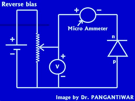
What is a Microammeter?
A microammeter is an electrical measuring instrument designed to measure very small currents, usually in the range of microamperes (μA). It is a type of ammeter that is highly sensitive and can detect minute changes in current flow. Microammeters are widely used in various applications, such as:
- Testing and troubleshooting electronic circuits
- Measuring leakage currents in capacitors and other components
- Monitoring the output of sensors and transducers
- Evaluating the performance of low-power devices
How Does a Microammeter Work?
A microammeter works on the principle of Ohm’s law, which states that the current flowing through a conductor is directly proportional to the voltage across it and inversely proportional to its resistance. In a microammeter, a small current is passed through a high-precision resistor, causing a voltage drop across it. This voltage drop is then amplified and displayed on a meter or a digital readout.
The basic components of a microammeter include:
- A high-precision resistor (shunt resistor)
- An operational amplifier (op-amp)
- A meter or digital display
- A power source (battery or DC Power Supply)
Designing the Microammeter Circuit
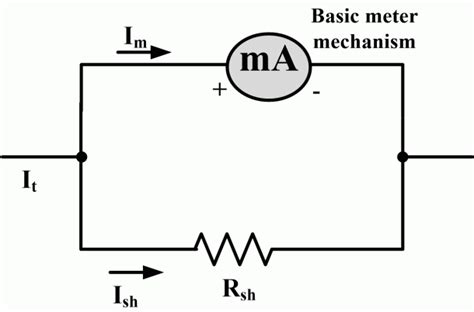
Step 1: Selecting the Shunt Resistor
The shunt resistor is the most critical component in a microammeter circuit. It determines the maximum current that can be measured and the resolution of the meter. The value of the shunt resistor is chosen based on the desired full-scale current range of the microammeter.
For example, if you want to measure currents up to 100 μA with a 1 V full-scale voltage, you would need a shunt resistor of:
R = V / I
R = 1 V / 100 μA
R = 10 kΩ
Here’s a table showing some common shunt resistor values for different current ranges:
| Current Range | Shunt Resistor Value |
|---|---|
| 10 μA | 100 kΩ |
| 50 μA | 20 kΩ |
| 100 μA | 10 kΩ |
| 500 μA | 2 kΩ |
| 1 mA | 1 kΩ |
Step 2: Choosing the Operational Amplifier
The operational amplifier (op-amp) is used to amplify the voltage drop across the shunt resistor and provide a suitable output for the meter or digital display. When selecting an op-amp for your microammeter circuit, consider the following factors:
- Input impedance: The op-amp should have a high input impedance to minimize loading effects on the shunt resistor.
- Bandwidth: The op-amp should have sufficient bandwidth to handle the expected frequency range of the measured currents.
- Noise: Low-noise op-amps are preferred to minimize the impact of noise on the measurements.
Some popular op-amps for microammeter circuits include:
- LM358: Dual op-amp, low power consumption, wide supply voltage range
- TL081: JFET-input op-amp, high input impedance, low noise
- OPA333: Single-supply op-amp, low quiescent current, rail-to-rail output
Step 3: Designing the Amplifier Circuit
The amplifier circuit is built around the op-amp and is responsible for amplifying the voltage drop across the shunt resistor. The gain of the amplifier is determined by the ratio of the feedback resistor (Rf) to the input resistor (Rin).
A basic non-inverting amplifier circuit is shown below:
        +Vcc
         |
        +-+
        |  \
        |   \
Vin ---+--- Rin ---+
        |          |
        +---+------+---------- Output
        |   |      |
        |   |      Rf
        |   |      |
        |  -+      |
        |   |      |
        +---+      |
         |         |
        GND       GND
The gain of the non-inverting amplifier is given by:
Gain = 1 + (Rf / Rin)
To achieve the desired full-scale voltage output (usually 1 V or 5 V), choose the appropriate values for Rf and Rin.
For example, if you want a gain of 100 with Rin = 1 kΩ, then:
Rf = (Gain – 1) * Rin
Rf = (100 – 1) * 1 kΩ
Rf = 99 kΩ
Step 4: Connecting the Meter or Digital Display
The output of the amplifier circuit is connected to a meter or digital display to provide a visual indication of the measured current. When using an analog meter, ensure that the meter’s full-scale deflection matches the amplifier’s output voltage.
For digital displays, you can use an analog-to-digital converter (ADC) to convert the amplifier’s output voltage into a digital value. Many microcontrollers, such as Arduino or Raspberry Pi, have built-in ADCs that can be used for this purpose.

Building the Microammeter Circuit
Now that you have designed your microammeter circuit, it’s time to build it. Follow these steps to assemble the components:
- Gather the necessary components:
- Shunt resistor
- Operational amplifier
- Feedback resistor (Rf)
- Input resistor (Rin)
- Meter or digital display
- Power source (battery or DC power supply)
- Breadboard or printed circuit board (PCB)
- Jumper wires
- Place the shunt resistor in series with the current path you want to measure.
- Connect the input of the op-amp to the shunt resistor using the input resistor (Rin).
- Connect the feedback resistor (Rf) between the output and the inverting input of the op-amp.
- Connect the non-inverting input of the op-amp to ground.
- Connect the power supply to the op-amp, providing the necessary positive and negative supply voltages.
- Connect the output of the op-amp to the meter or digital display.
- Double-check all connections to ensure they are correct and secure.
Calibrating the Microammeter
After assembling the microammeter circuit, it is essential to calibrate it to ensure accurate readings. Follow these steps to calibrate your microammeter:
- Connect a known current source (e.g., a precision current source or a resistor with a known voltage applied) to the input of the microammeter.
- Adjust the gain of the amplifier circuit by changing the value of the feedback resistor (Rf) until the meter or digital display shows the correct current value.
- Repeat the process with different known current values to verify the accuracy of the microammeter across its full range.
- If necessary, fine-tune the gain of the amplifier circuit to achieve the desired accuracy.
Troubleshooting Tips
If you encounter issues while building or using your microammeter, consider the following troubleshooting tips:
- Double-check all connections to ensure they are correct and secure.
- Verify that the polarity of the power supply and the meter or digital display is correct.
- Check the value and tolerance of the shunt resistor and the feedback resistor (Rf) to ensure they are accurate.
- Ensure that the op-amp is functioning correctly by measuring its output voltage with a Multimeter.
- Check for any shorts or open circuits in the wiring.
- Verify that the current being measured is within the range of the microammeter.
Applications of Microammeters
Microammeters have a wide range of applications in electronics, research, and industry. Some common applications include:
- Measuring leakage currents in capacitors, diodes, and other components
- Monitoring the output of sensors, such as photodiodes or temperature sensors
- Evaluating the performance of low-power devices, such as wearable electronics or IoT sensors
- Troubleshooting and debugging electronic circuits
- Measuring the current consumption of battery-powered devices
- Investigating the electrical properties of materials, such as semiconductors or insulators
Frequently Asked Questions (FAQ)
- Q: What is the difference between a microammeter and a standard ammeter?
A: A microammeter is designed to measure very small currents, typically in the microampere (μA) range, while a standard ammeter is used to measure larger currents, usually in the milliampere (mA) or ampere (A) range. Microammeters are more sensitive and have a higher resolution than standard ammeters. - Q: Can I use a microammeter to measure AC currents?
A: The simple microammeter circuit described in this article is designed to measure DC currents. To measure AC currents, you would need to modify the circuit to include a rectifier and a filter to convert the AC signal to DC. Alternatively, you can use a specialized AC current probe or a true RMS meter designed for measuring AC currents. - Q: What is the purpose of the shunt resistor in a microammeter circuit?
A: The shunt resistor is used to convert the current being measured into a voltage drop that can be amplified by the op-amp. The value of the shunt resistor determines the maximum current that can be measured and the resolution of the microammeter. - Q: How do I choose the appropriate op-amp for my microammeter circuit?
A: When selecting an op-amp for your microammeter circuit, consider factors such as input impedance, bandwidth, noise, and power consumption. Choose an op-amp with high input impedance to minimize loading effects on the shunt resistor, sufficient bandwidth to handle the expected frequency range of the measured currents, and low noise to minimize the impact of noise on the measurements. - Q: Can I use a microcontroller with a built-in ADC to display the measured current?
A: Yes, you can use a microcontroller with a built-in ADC, such as an Arduino or Raspberry Pi, to convert the analog output voltage of the microammeter circuit into a digital value. The digital value can then be displayed on an LCD, OLED display, or sent to a computer for further processing and analysis.
Conclusion
Building a simple Micro Ampere Meter circuit is a valuable skill for anyone interested in electronics and electrical measurements. By understanding the principles behind a microammeter and following the steps outlined in this article, you can construct your own microammeter using readily available components.
Remember to select the appropriate shunt resistor value for your desired current range, choose a suitable op-amp for your application, and carefully design and assemble the amplifier circuit. Don’t forget to calibrate your microammeter to ensure accurate readings and follow the troubleshooting tips if you encounter any issues.
With your own microammeter, you can explore a wide range of applications in electronics, research, and industry, from measuring leakage currents in components to evaluating the performance of low-power devices. As you gain more experience with microammeters, you can expand your skills and tackle more advanced projects involving sensitive current measurements.
No responses yet