Introduction to Micro Ampere Meters
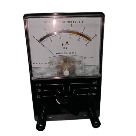
A micro ampere meter, also known as a microammeter or µA meter, is an electrical measuring instrument designed to measure very small electric currents, typically in the range of microamperes (µA). These meters are essential tools for various applications in electronics, scientific research, and industrial processes where precise measurement of low currents is crucial.
Micro ampere meters are highly sensitive and require special design considerations to ensure accurate readings. They are used in a wide range of fields, including:
- Electronics testing and troubleshooting
- Medical equipment monitoring
- Environmental monitoring
- Scientific research and experiments
Importance of Micro Ampere Meters
Measuring small currents accurately is essential in many applications where the flow of electrons is minimal. Some examples include:
-
Leakage current measurement: Micro ampere meters are used to measure leakage currents in electronic components, such as capacitors and insulators, to ensure they meet the required specifications and safety standards.
-
Sensor monitoring: Many sensors, such as photodiodes, thermocouples, and PH Sensors, generate small currents that need to be measured precisely. Micro ampere meters enable accurate monitoring of these sensors.
-
Battery health monitoring: Micro ampere meters are used to measure the small currents drawn by electronic devices in standby mode, which can help determine the health and remaining capacity of batteries.
How Micro Ampere Meters Work
Micro ampere meters work on the principle of measuring the voltage drop across a shunt resistor when a small current passes through it. The shunt resistor is a low-value, high-precision resistor connected in series with the circuit being measured.
Shunt Resistor
The shunt resistor is the key component in a micro ampere meter. It is designed to have a very low resistance value, typically in the range of milliohms (mΩ) to a few ohms (Ω). The low resistance minimizes the impact of the meter on the circuit being measured, ensuring accurate readings.
The value of the shunt resistor is chosen based on the expected current range and the desired voltage drop across the resistor. The voltage drop is usually kept small to minimize the power dissipation in the resistor and to avoid affecting the circuit being measured.
Voltage Measurement
The voltage drop across the shunt resistor is proportional to the current flowing through it, according to Ohm’s law:
V = I × R
Where:
– V is the voltage drop across the resistor (in volts)
– I is the current flowing through the resistor (in amperes)
– R is the resistance of the shunt resistor (in ohms)
By measuring the voltage drop across the shunt resistor and knowing its resistance value, the current can be calculated using the above formula.
Amplification and Display
Since the voltage drop across the shunt resistor is typically very small, it needs to be amplified before it can be displayed on the meter. This is achieved using a high-gain, low-noise amplifier circuit.
The amplified voltage is then fed to an analog or digital display, which shows the measured current value. Analog micro ampere meters use a moving coil meter movement, while digital meters use an analog-to-digital converter (ADC) and a digital display.
Micro Ampere Meter Circuit Diagram
A basic micro ampere meter circuit consists of the following components:
- Shunt resistor
- Amplifier circuit
- Display (analog or digital)
- Power supply
Here is a simplified circuit diagram of a micro ampere meter:
       +---------+
       |         |
       |  Shunt  |
       | Resistor|
       |         |
       +---+--+--+
           |  |
           |  |
           |  |
           |  |
           |  |
       +---+--+--+
       |         |
       |Amplifier|
       | Circuit |
       |         |
       +---+-----+
           |
           |
       +---+-----+
       |         |
       | Display |
       |         |
       +---------+
Shunt Resistor Selection
The selection of the shunt resistor depends on the expected current range and the desired voltage drop. The resistance value can be calculated using Ohm’s law:
R = V / I
Where:
– R is the resistance of the shunt resistor (in ohms)
– V is the desired voltage drop across the resistor (in volts)
– I is the maximum expected current (in amperes)
For example, if the maximum expected current is 100 µA and the desired voltage drop is 10 mV, the shunt resistor value would be:
R = 10 mV / 100 µA = 100 Ω
Amplifier Circuit Design
The amplifier circuit in a micro ampere meter is typically based on an operational amplifier (op-amp). The op-amp is configured as a non-inverting amplifier, which amplifies the voltage drop across the shunt resistor.
The gain of the amplifier is determined by the ratio of the feedback resistor (Rf) to the input resistor (Rin):
Gain = 1 + (Rf / Rin)
The values of Rf and Rin are chosen to provide the desired gain and to match the input range of the display.
Here is an example of a non-inverting amplifier circuit using an op-amp:
               +--+
               |  |
               |  |
               |  |
              ++-++
             |     |
       +-----+     +-----+
       |                 |
       | Rin          Rf |
       |                 |
       +-----+     +-----+
             |     |
             +     +
             |     |
            -+     +-
             |  -  |
             +--+--+
                |
                |
                +-----+
                      |
                      |
                      +
Display Selection
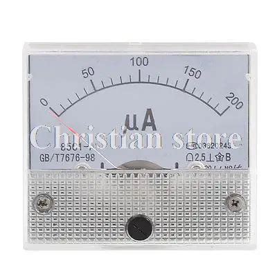
The display in a micro ampere meter can be either analog or digital. Analog meters use a moving coil meter movement, which consists of a coil of wire suspended in a magnetic field. As current flows through the coil, it generates a magnetic field that interacts with the permanent magnet, causing the coil to rotate. The rotation is proportional to the current and is indicated by a pointer on a calibrated scale.
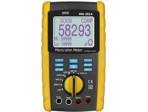
Digital meters use an analog-to-digital converter (ADC) to convert the amplified voltage into a digital value, which is then displayed on a digital readout, such as an LCD or LED display.
The choice between analog and digital displays depends on factors such as the required resolution, accuracy, and reading frequency.

Calibration and Maintenance
Proper calibration and maintenance are essential for ensuring the accuracy and reliability of micro ampere meters. The following steps should be taken:
-
Regular calibration: Micro ampere meters should be calibrated periodically using a known reference current source to ensure the accuracy of readings.
-
Zero adjustment: Before each use, the meter should be checked for zero offset and adjusted if necessary. This is typically done using a built-in zero adjustment potentiometer.
-
Proper storage: When not in use, micro ampere meters should be stored in a clean, dry environment to prevent damage from dust, moisture, and other environmental factors.
-
Handling with care: Micro ampere meters are sensitive instruments and should be handled with care to avoid mechanical shock, vibration, and excessive current overloads.
Applications of Micro Ampere Meters
Micro ampere meters find applications in various fields, including:
-
Electronics testing and troubleshooting: Micro ampere meters are used to measure leakage currents, bias currents, and other small currents in electronic circuits during testing and troubleshooting.
-
Medical equipment monitoring: Many medical devices, such as pacemakers, defibrillators, and patient monitors, require precise measurement of small currents for proper functioning and safety.
-
Environmental monitoring: Micro ampere meters are used in environmental monitoring applications, such as measuring the conductivity of water samples or the output of gas sensors.
-
Scientific research: In scientific research, micro ampere meters are used to measure small currents in experiments involving electrochemistry, photonics, and materials science.
-
Automotive industry: In the automotive industry, micro ampere meters are used to measure leakage currents in vehicle electrical systems, helping to diagnose issues related to battery drain and parasitic loads.
Advantages and Limitations
Micro ampere meters offer several advantages:
- High sensitivity and resolution, enabling the measurement of very small currents.
- Wide measurement range, typically from nanoamperes to milliamperes.
- Non-invasive measurement, minimizing the impact on the circuit being measured.
- Versatility, with applications in various fields.
However, micro ampere meters also have some limitations:
- Susceptibility to electromagnetic interference (EMI) due to their high sensitivity.
- Requirement for proper shielding and grounding to minimize noise and interference.
- Sensitivity to temperature variations, which can affect the accuracy of readings.
- Higher cost compared to standard ammeter.
Frequently Asked Questions (FAQ)
-
What is the difference between a micro ampere meter and a standard ammeter?
A micro ampere meter is designed to measure very small currents, typically in the range of microamperes (µA), while a standard ammeter measures currents in the range of milliamperes (mA) to amperes (A). Micro ampere meters are more sensitive and have a higher resolution than standard ammeters. -
Can a micro ampere meter be used to measure AC currents?
Most micro ampere meters are designed to measure DC currents. However, some specialized meters, known as AC micro ampere meters, are capable of measuring small AC currents. These meters typically use a rectifier circuit to convert the AC current into a DC current before measurement. -
How do I choose the right shunt resistor for my micro ampere meter?
The shunt resistor value depends on the expected current range and the desired voltage drop across the resistor. To calculate the shunt resistor value, use Ohm’s law: R = V / I, where R is the resistance, V is the desired voltage drop, and I is the maximum expected current. Choose a resistor with a low temperature coefficient and high precision for accurate measurements. -
What is the purpose of the amplifier circuit in a micro ampere meter?
The amplifier circuit in a micro ampere meter is used to amplify the small voltage drop across the shunt resistor, making it suitable for display on an analog or digital readout. The amplifier circuit is typically based on an operational amplifier (op-amp) configured as a non-inverting amplifier, with the gain determined by the ratio of the feedback resistor to the input resistor. -
How often should a micro ampere meter be calibrated?
The calibration frequency of a micro ampere meter depends on factors such as the usage frequency, environmental conditions, and required accuracy. As a general guideline, micro ampere meters should be calibrated at least once a year or as recommended by the manufacturer. More frequent calibration may be necessary for critical applications or harsh environments.
Conclusion
Micro ampere meters are essential tools for measuring small currents in various applications, from electronics testing and medical equipment monitoring to environmental monitoring and scientific research. These meters work by measuring the voltage drop across a shunt resistor and amplifying the signal for display on an analog or digital readout.
Proper selection of the shunt resistor, amplifier circuit design, and display type are crucial for accurate and reliable measurements. Regular calibration and maintenance are also essential to ensure the long-term performance of micro ampere meters.
By understanding the basics, circuit diagram, and applications of micro ampere meters, engineers, technicians, and researchers can effectively use these instruments to measure small currents and gain valuable insights into the behavior of electronic systems and devices.
No responses yet