Introduction to Capacitor Selection
Capacitors are essential components in electronic circuits, used for storing electrical energy, filtering signals, and smoothing out voltage fluctuations. With a wide variety of capacitor types available, each with its own unique properties and characteristics, selecting the right capacitor for your specific application can be a challenging task. In this article, we will explore the different types of capacitors, their key features, and the factors to consider when choosing the appropriate capacitor for your project.
Types of Capacitors
Ceramic Capacitors
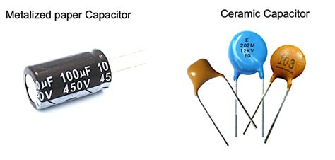
Ceramic capacitors are widely used in electronic circuits due to their low cost, small size, and good temperature stability. They are made from alternating layers of ceramic dielectric material and metal electrodes. Ceramic capacitors are available in various dielectric types, such as Class 1 (C0G/NP0) and Class 2 (X7R, X5R, Y5V), each with different temperature coefficients and voltage ratings.
Advantages of Ceramic Capacitors
- Low cost
- Small size
- Good temperature stability
- High voltage ratings
- Low ESR (Equivalent Series Resistance)
Disadvantages of Ceramic Capacitors
- Limited capacitance values
- Prone to microphonic effects
- Brittle and susceptible to mechanical stress
Electrolytic Capacitors
Electrolytic capacitors are polarized capacitors that offer high capacitance values in a compact size. They consist of a metal foil anode, a liquid or solid electrolyte, and a cathode foil. The two main types of electrolytic capacitors are aluminum electrolytic capacitors and tantalum electrolytic capacitors.
Aluminum Electrolytic Capacitors
Aluminum electrolytic capacitors are commonly used in power supply filtering, audio coupling, and decoupling applications. They provide high capacitance values, typically ranging from 1 µF to several thousand µF, and are available in various voltage ratings.
Advantages of Aluminum Electrolytic Capacitors
- High capacitance values
- Compact size
- Low cost
- Wide operating temperature range
Disadvantages of Aluminum Electrolytic Capacitors
- Polarized (must be connected with correct polarity)
- Limited shelf life due to electrolyte evaporation
- Higher ESR compared to other capacitor types
- Relatively high leakage current
Tantalum Electrolytic Capacitors
Tantalum electrolytic capacitors offer higher capacitance values per unit volume compared to aluminum electrolytic capacitors. They are known for their stability, low leakage current, and long shelf life. Tantalum capacitors are commonly used in portable devices, medical equipment, and military applications.
Advantages of Tantalum Electrolytic Capacitors
- High capacitance density
- Low leakage current
- Long shelf life
- Good temperature stability
Disadvantages of Tantalum Electrolytic Capacitors
- Higher cost compared to aluminum electrolytic capacitors
- Polarized
- Sensitive to voltage spikes and reverse voltage
- Potential for ignition under certain conditions
Film Capacitors
Film capacitors are non-polarized capacitors that use a thin plastic film as the dielectric material. They offer good stability, low losses, and high insulation resistance. The most common types of film capacitors are polyester (PET), polypropylene (PP), and polycarbonate (PC).
Advantages of Film Capacitors
- Non-polarized
- Low losses and high insulation resistance
- Good temperature stability
- Low ESR
- High voltage ratings
Disadvantages of Film Capacitors
- Larger size compared to ceramic and electrolytic capacitors
- Higher cost compared to ceramic capacitors
- Limited capacitance values
Mica Capacitors
Mica capacitors are made from stacked sheets of mica dielectric material and metal foil electrodes. They are known for their high stability, low losses, and excellent temperature characteristics. Mica capacitors are commonly used in high-frequency applications, such as RF circuits and oscillators.
Advantages of Mica Capacitors
- High stability and accuracy
- Low losses and high Q factor
- Wide operating temperature range
- High voltage ratings
- Low temperature coefficient
Disadvantages of Mica Capacitors
- High cost compared to other capacitor types
- Limited capacitance values
- Larger size compared to ceramic capacitors
Supercapacitors (Ultracapacitors)
Supercapacitors, also known as ultracapacitors or electric double-layer capacitors (EDLCs), are high-capacity energy storage devices that bridge the gap between conventional capacitors and batteries. They offer very high capacitance values, typically in the range of several farads to thousands of farads, and can deliver high power density.
Advantages of Supercapacitors
- Very high capacitance values
- High power density
- Fast charge and discharge cycles
- Long lifespan (hundreds of thousands of cycles)
- Wide operating temperature range
Disadvantages of Supercapacitors
- Lower energy density compared to batteries
- Higher self-discharge rate compared to conventional capacitors
- Higher cost compared to other capacitor types
- Limited voltage ratings (typically 2.7 V to 3.0 V per cell)

Factors to Consider When Selecting a Capacitor
Capacitance Value
The capacitance value is the primary factor to consider when selecting a capacitor. It determines the amount of electrical energy the capacitor can store. The required capacitance value depends on the specific application and circuit requirements.
Voltage Rating
The voltage rating of a capacitor indicates the maximum voltage that can be applied across its terminals without causing damage. It is essential to choose a capacitor with a voltage rating higher than the maximum expected voltage in the circuit to ensure safe and reliable operation.
Temperature Coefficient
The temperature coefficient of a capacitor represents the change in capacitance value with respect to temperature. Different capacitor types have different temperature coefficients, which can affect circuit performance. It is important to consider the operating temperature range of the application and choose a capacitor with a suitable temperature coefficient.
Equivalent Series Resistance (ESR)
ESR is the inherent resistance of a capacitor that contributes to power loss and affects the capacitor’s performance at high frequencies. Low-ESR capacitors are preferred for applications that require fast switching or high-frequency operation, such as power supply decoupling and high-speed digital circuits.
Tolerance
Capacitor tolerance indicates the allowable variation in capacitance value from the nominal value. Tighter tolerance capacitors are required for applications that demand precise capacitance values, such as timing circuits and filters.
Size and Package
The physical size and package of a capacitor are important considerations, especially in space-constrained applications. Smaller capacitor packages, such as surface-mount devices (SMDs), are commonly used in compact electronic designs.
Leakage Current
Leakage current is the small current that flows through a capacitor when a voltage is applied across its terminals. Low leakage current is desirable in applications where the capacitor is used for long-term energy storage or in low-power circuits.
Dielectric Absorption
Dielectric absorption refers to the tendency of a capacitor to retain a residual charge after being discharged. It can affect the accuracy of timing circuits and sample-and-hold applications. Capacitors with low dielectric absorption, such as polypropylene film capacitors, are preferred for these applications.

Capacitor Selection Table
| Capacitor Type | Capacitance Range | Voltage Range | Temperature Range | Applications |
|---|---|---|---|---|
| Ceramic (Class 1) | 1 pF to 1 nF | 16 V to 100 V | -55°C to +125°C | High-frequency, temperature-compensating |
| Ceramic (Class 2) | 100 pF to 10 µF | 6.3 V to 630 V | -55°C to +85°C | General-purpose, decoupling, filtering |
| Aluminum Electrolytic | 1 µF to 1 F | 6.3 V to 450 V | -40°C to +85°C | Power supply filtering, audio coupling, decoupling |
| Tantalum Electrolytic | 0.1 µF to 1000 µF | 2.5 V to 50 V | -55°C to +125°C | Portable devices, medical equipment, military applications |
| Film (Polyester) | 1 nF to 10 µF | 50 V to 630 V | -55°C to +125°C | General-purpose, audio, motor run capacitors |
| Film (Polypropylene) | 100 pF to 10 µF | 63 V to 2000 V | -55°C to +105°C | Power supply filtering, audio, high-voltage applications |
| Mica | 1 pF to 10 nF | 50 V to 2500 V | -55°C to +125°C | High-frequency, RF circuits, oscillators |
| Supercapacitor | 1 F to 3000 F | 2.5 V to 3.0 V | -40°C to +65°C | Energy storage, backup power, peak power assistance |

Frequently Asked Questions (FAQ)
1. How do I determine the required capacitance value for my application?
The required capacitance value depends on the specific application and circuit requirements. Factors such as the desired time constant, cut-off frequency, and energy storage needs should be considered. It is recommended to refer to the application notes or consult with an experienced engineer to determine the appropriate capacitance value.
2. Can I use a capacitor with a higher voltage rating than my circuit’s operating voltage?
Yes, you can use a capacitor with a higher voltage rating than your circuit’s operating voltage. In fact, it is recommended to choose a capacitor with a voltage rating higher than the maximum expected voltage in the circuit to ensure safe and reliable operation. However, using a capacitor with a significantly higher voltage rating than necessary may result in a larger and more expensive component.
3. What is the difference between polarized and non-polarized capacitors?
Polarized capacitors, such as electrolytic capacitors, have a specific positive and negative terminal and must be connected with the correct polarity in a circuit. Incorrect polarity connection can lead to capacitor damage or even explosion. Non-polarized capacitors, such as ceramic, film, and mica capacitors, do not have a specific polarity and can be connected in either direction in a circuit.
4. How do I select the appropriate voltage rating for my capacitor?
The voltage rating of a capacitor should be selected based on the maximum expected voltage in the circuit. It is recommended to choose a capacitor with a voltage rating at least 50% higher than the maximum expected voltage to provide a safety margin. For example, if your circuit operates at 10 V, choose a capacitor with a voltage rating of at least 15 V.
5. Can I substitute a capacitor with a different type but the same capacitance and voltage rating?
While it is possible to substitute a capacitor with a different type that has the same capacitance and voltage rating, it is important to consider other factors such as temperature coefficient, ESR, and package size. Different capacitor types have different characteristics that may affect circuit performance. It is recommended to consult the capacitor datasheets and application notes to ensure proper substitution.
Conclusion
Selecting the right capacitor for your application is crucial for ensuring optimal circuit performance and reliability. By understanding the different types of capacitors, their key features, and the factors to consider during the selection process, you can make informed decisions when designing your electronic projects. Always refer to the capacitor datasheets, application notes, and consult with experienced engineers if you have any doubts or specific requirements.
Remember, the choice of capacitor depends on various factors such as capacitance value, voltage rating, temperature coefficient, ESR, tolerance, size, leakage current, and dielectric absorption. By carefully considering these factors and matching them with your application needs, you can select the most suitable capacitor for your project.
As technology advances, new capacitor types and materials may emerge, offering improved performance and capabilities. Stay updated with the latest developments in capacitor technology and be open to exploring new options when appropriate.
With the knowledge gained from this article, you are now better equipped to navigate the world of capacitor selection and make informed choices for your electronic projects. Remember, the right capacitor selection can make a significant difference in the performance, reliability, and longevity of your circuits.

No responses yet