What is a Capacitor?
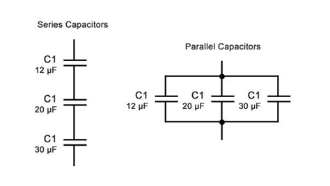
A capacitor is a passive two-terminal electrical component that stores electrical energy in an electric field. It consists of two conducting plates separated by an insulating material called a dielectric. When a voltage is applied across the capacitor, electric charges of equal magnitude but opposite polarity build up on each plate, creating an electric field between them. The capacitor’s ability to store energy in this field makes it a fundamental component in many electronic circuits.
Types of Capacitors
There are several types of capacitors, each with its own characteristics and applications:
| Type | Description |
|---|---|
| Ceramic | Inexpensive, small, and stable, but low capacitance |
| Electrolytic | High capacitance, polarized, and prone to leakage |
| Film | Stable, low leakage, and high voltage ratings |
| Tantalum | High capacitance, small size, and polarized |
| Variable | Capacitance can be adjusted, used in tuning circuits |
| Supercapacitor | Extremely high capacitance, used for energy storage |
Role of Capacitors in Circuit Boards
Capacitors play several essential roles in electronic circuits:
1. Energy Storage
One of the primary functions of a capacitor is to store electrical energy. When a voltage is applied to a capacitor, it accumulates charge on its plates, storing energy in the electric field between them. This stored energy can be released back into the circuit when needed.
2. Filtering
Capacitors are often used in combination with resistors and inductors to create filters that can block or pass specific frequencies. This is particularly useful in power supply circuits, where capacitors help smooth out voltage ripples and reduce noise.
3. Coupling and Decoupling
In multi-stage amplifiers or other cascaded circuits, capacitors are used for coupling signals between stages while blocking DC voltage. This allows the AC signal to pass through while preventing unwanted DC offsets from affecting subsequent stages.
Decoupling Capacitors, on the other hand, are placed near integrated circuits (ICs) to provide a stable voltage supply by filtering out high-frequency noise and preventing voltage drops caused by sudden current demands.
4. Timing and Oscillation
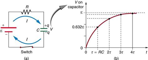
Capacitors are essential components in timing and oscillation circuits. When combined with resistors, they form RC networks that introduce time delays or create oscillations at specific frequencies. This principle is used in 555 timers, LC Oscillators, and other time-dependent circuits.
5. Compensation and Tuning
In some circuits, capacitors are used for compensation or tuning purposes. For example, in amplifiers, capacitors can be used to compensate for frequency-dependent gain variations, ensuring a flat frequency response. In tuned circuits, variable capacitors allow for precise frequency adjustment.

Capacitor Specifications
When selecting a capacitor for a circuit board, several key specifications must be considered:
1. Capacitance
Capacitance is the primary characteristic of a capacitor, measured in farads (F). It represents the capacitor’s ability to store charge. Common capacitance values range from picofarads (pF) to millifarads (mF), depending on the application.
2. Voltage Rating
The voltage rating specifies the maximum voltage that can be safely applied to the capacitor without causing dielectric breakdown or damage. It is crucial to choose a capacitor with a voltage rating higher than the expected maximum voltage in the circuit.
3. Tolerance
Capacitor tolerance indicates the allowable variation in capacitance from the nominal value, expressed as a percentage. Common tolerances are ±5%, ±10%, and ±20%. Tighter tolerances are required for precision applications, while looser tolerances may be acceptable for general-purpose use.
4. Temperature Coefficient
The temperature coefficient describes how a capacitor’s capacitance varies with temperature changes. It is expressed in parts per million per degree Celsius (ppm/°C). Capacitors with low temperature coefficients are preferred for applications where stable performance over a wide temperature range is necessary.
5. Equivalent Series Resistance (ESR)
ESR represents the inherent resistance within a capacitor, which can affect its performance at high frequencies. Lower ESR values are desirable for applications involving high-frequency signals or fast transient response.
6. Leakage Current
Leakage current refers to the small current that flows through a capacitor when a DC voltage is applied. It is typically specified in microamps (μA) or nanoamps (nA). Low leakage current is essential for applications where long-term charge retention is critical, such as sample-and-hold circuits.

Capacitor Placement on Circuit Boards
Proper placement of capacitors on a circuit board is crucial for optimal performance and minimizing unwanted effects:
1. Decoupling Capacitors
Decoupling capacitors should be placed as close as possible to the power pins of ICs to minimize the inductance of the power supply traces. This helps prevent voltage drops and high-frequency noise from affecting the IC’s performance.
2. Signal Path Capacitors
Capacitors used in signal paths, such as coupling or filtering capacitors, should be placed close to the relevant components to minimize stray inductance and capacitance. This helps maintain signal integrity and reduces the risk of unwanted resonances or oscillations.
3. Grounding
Proper grounding is essential for capacitor performance. The ground connections of capacitors should be as short and direct as possible to minimize ground loop impedance and reduce noise coupling. In some cases, a dedicated ground plane may be necessary to provide a low-impedance return path.
4. Thermal Considerations
Capacitors, especially electrolytic and tantalum types, are sensitive to temperature. They should be placed away from heat-generating components and in areas with adequate airflow to prevent overheating and premature failure.

Capacitor Selection Guide
Choosing the right capacitor for a specific application involves considering several factors:
| Factor | Consideration |
|---|---|
| Capacitance | Determine the required capacitance value based on circuit needs |
| Voltage Rating | Select a voltage rating higher than the maximum expected voltage |
| Tolerance | Choose the appropriate tolerance based on precision requirements |
| Temperature Stability | Consider the operating temperature range and select accordingly |
| Frequency Response | Evaluate the capacitor’s performance at the relevant frequencies |
| Size and Package | Select a package that fits the available space on the circuit board |
| Cost | Balance performance requirements with budget constraints |
Capacitor Failure Modes and Troubleshooting
Capacitors can fail due to various reasons, leading to circuit malfunctions. Common failure modes include:
1. Open Circuit
An open-circuit capacitor acts as an open switch, blocking current flow. This can cause signal interruptions, oscillation, or complete circuit failure. Open-circuit capacitors can be identified using a multimeter or by observing the circuit’s behavior.
2. Short Circuit
A short-circuited capacitor acts as a closed switch, allowing current to flow freely. This can lead to excessive current draw, overheating, and damage to other components. Short-circuited capacitors can be detected using a multimeter or by measuring the voltage across the capacitor.
3. Leakage
Excessive leakage current can cause a capacitor to discharge prematurely, leading to performance issues or circuit malfunctions. Leakage can be caused by age, overheating, or dielectric breakdown. Leakage can be measured using a high-resistance multimeter or a dedicated leakage meter.
4. Capacitance Drift
Capacitance drift occurs when a capacitor’s capacitance value changes over time or with temperature. This can lead to detuning, oscillation, or other performance issues. Capacitance drift can be detected by measuring the capacitance at different temperatures or by monitoring the circuit’s performance over time.
Frequently Asked Questions (FAQ)
1. What is the difference between polarized and non-polarized capacitors?
Polarized capacitors, such as electrolytic and tantalum capacitors, have a specific positive and negative terminal and must be connected with the correct polarity. Non-polarized capacitors, such as ceramic and film capacitors, can be connected in either direction.
2. Can I replace a capacitor with one that has a different capacitance value?
In some cases, a capacitor can be replaced with one that has a slightly different capacitance value. However, it is essential to consider the impact on circuit performance, such as time constants, filtering, or tuning. It is generally best to replace a capacitor with one of the same capacitance value or as close as possible.
3. What happens if I use a capacitor with a voltage rating lower than the circuit voltage?
Using a capacitor with a voltage rating lower than the circuit voltage can lead to dielectric breakdown, short-circuiting, and permanent damage to the capacitor and potentially other components. Always use a capacitor with a voltage rating higher than the maximum expected voltage in the circuit.
4. How do I know if a capacitor is faulty?
A faulty capacitor can be identified through visual inspection (bulging, leaking, or discoloration), multimeter tests (open circuit, short circuit, or capacitance out of tolerance), or by observing circuit misbehavior (oscillation, signal distortion, or malfunctions). In some cases, specialized equipment, such as an ESR meter or leakage tester, may be necessary to diagnose capacitor issues.
5. Can I use a non-polarized capacitor in place of a polarized one?
Generally, it is not recommended to use a non-polarized capacitor in place of a polarized one. Polarized capacitors are designed to handle the specific polarity requirements of the circuit and have higher capacitance values for a given size. Using a non-polarized capacitor in a circuit designed for a polarized one may lead to performance issues or even damage to the capacitor or other components.
Conclusion
Capacitors are essential components in electronic circuits, serving various purposes, such as energy storage, filtering, coupling, and timing. Understanding the different types of capacitors, their specifications, and their roles in circuit boards is crucial for designing and troubleshooting electronic systems.
Proper selection and placement of capacitors are critical for ensuring optimal circuit performance and reliability. By considering factors such as capacitance, voltage rating, tolerance, and temperature stability, designers can choose the most suitable capacitors for their applications.
Regular inspection and maintenance of capacitors can help prevent failures and extend the lifespan of electronic devices. By recognizing common failure modes and using appropriate troubleshooting techniques, technicians can quickly identify and replace faulty capacitors, minimizing downtime and repair costs.
As technology advances, new capacitor materials and designs are being developed to meet the ever-increasing demands of modern electronics. Staying up-to-date with the latest capacitor technologies and best practices is essential for engineers and technicians working in the field of electronics.
By understanding the fundamentals of capacitors and their applications in circuit boards, designers and technicians can create more efficient, reliable, and robust electronic systems.

No responses yet