Introduction
In today’s world, digital thermometers have become an essential tool in various industries, from healthcare to engineering. These devices offer accurate temperature measurements and are easy to use, making them a popular choice for many applications. If you’re interested in learning how to design a digital thermometer PCB (Printed Circuit Board), this article will guide you through the process in 7 simple steps.
What is a PCB Thermometer?
A PCB thermometer is a digital thermometer that uses a printed circuit board to measure and display temperature. The PCB contains various components, such as a temperature sensor, microcontroller, display, and other electronic components that work together to provide accurate temperature readings.

Step 1: Choose the Right Temperature Sensor
The first step in designing a digital thermometer PCB is to choose the right temperature sensor. There are several types of temperature sensors available, each with its own advantages and disadvantages. Some of the most common types include:
Thermistors
Thermistors are resistors that change their resistance based on temperature. They are inexpensive, easy to use, and offer a wide temperature range. However, they have a non-linear response, which means that their resistance does not change linearly with temperature.
RTDs (Resistance Temperature Detectors)
RTDs are made of pure metals, such as platinum or nickel, and offer high accuracy and stability. They have a linear response, which makes them easier to calibrate than thermistors. However, they are more expensive and require more complex circuitry.
Thermocouples
Thermocouples consist of two dissimilar metals joined together at one end. They generate a voltage proportional to the temperature difference between the two ends. Thermocouples are rugged, can measure a wide temperature range, and are suitable for harsh environments. However, they require cold junction compensation and have lower accuracy compared to RTDs.
| Sensor Type | Advantages | Disadvantages |
|---|---|---|
| Thermistor | – Inexpensive – Easy to use – Wide temperature range |
– Non-linear response – Lower accuracy compared to RTDs |
| RTD | – High accuracy – Stability – Linear response |
– Expensive – Complex circuitry |
| Thermocouple | – Rugged – Wide temperature range – Suitable for harsh environments |
– Requires cold junction compensation – Lower accuracy compared to RTDs |

Step 2: Design the Sensor Interface Circuit
Once you have selected the temperature sensor, the next step is to design the sensor interface circuit. This circuit conditions the sensor’s output signal and converts it into a form that the microcontroller can read. The interface circuit depends on the type of sensor you choose.
For example, if you choose a thermistor, you can use a voltage divider circuit to convert the thermistor’s resistance into a voltage that the microcontroller can read. If you choose an RTD, you may need to use a Wheatstone bridge circuit to convert the RTD’s resistance into a voltage.

Step 3: Select the Microcontroller
The microcontroller is the brain of the digital thermometer PCB. It reads the sensor’s output, processes the data, and displays the temperature on the screen. When selecting a microcontroller, consider the following factors:
- Number of analog and digital I/O pins required
- Memory size (RAM and Flash)
- Processing speed
- Power consumption
- Cost
Some popular microcontrollers for digital thermometer PCBs include:
- Arduino (e.g., Arduino Uno, Arduino Nano)
- PIC microcontrollers (e.g., PIC16F, PIC18F)
- ATmega microcontrollers (e.g., ATmega328, ATmega2560)
Step 4: Design the Display Circuit
The display circuit is responsible for showing the measured temperature on the screen. There are several types of displays you can use, such as:
- LCD (Liquid Crystal Display)
- OLED (Organic Light-Emitting Diode)
- 7-segment LED display
When designing the display circuit, consider the display’s power requirements, communication protocol (e.g., I2C, SPI), and the number of pins required to interface with the microcontroller.
Step 5: Develop the Firmware
The firmware is the software that runs on the microcontroller and controls the digital thermometer’s operation. To develop the firmware, you’ll need to:
- Set up the development environment (e.g., Arduino IDE, MPLAB X IDE)
- Write the code to read the sensor’s output, process the data, and display the temperature
- Implement any additional features, such as temperature alarms or data logging
- Test and debug the code
When writing the firmware, consider the following best practices:
- Use meaningful variable and function names
- Comment your code to make it easier to understand
- Use libraries and functions to simplify the code
- Optimize the code for performance and memory usage
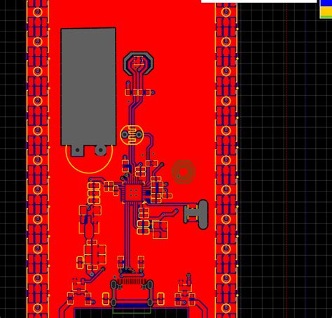
Step 6: Design the PCB Layout
Once you have designed the schematic and developed the firmware, the next step is to design the PCB layout. The PCB layout is the physical arrangement of components and traces on the circuit board. When designing the PCB layout, consider the following factors:
- Component placement for optimal performance and ease of assembly
- Trace width and spacing to minimize noise and interference
- Ground planes to reduce electromagnetic interference (EMI)
- Thermal management to dissipate heat from components
- Manufacturing constraints, such as minimum trace width and spacing
You can use PCB design software, such as Eagle, KiCad, or Altium Designer, to create the PCB layout.
Step 7: Manufacture and Test the PCB
The final step is to manufacture and test the PCB. You can either manufacture the PCB yourself using a PCB milling machine or send the design files to a PCB fabrication service. Once you have the manufactured PCB, assemble the components and test the digital thermometer to ensure it works as expected.
During testing, consider the following:
- Verify the accuracy of the temperature measurements using a reference thermometer
- Test the thermometer’s response time and stability
- Check for any errors or unexpected behavior in the firmware
- Ensure the display is readable and updates correctly
If you encounter any issues during testing, troubleshoot the problem by checking the connections, components, and firmware code.
FAQs
-
What is the best temperature sensor for a digital thermometer PCB?
The best temperature sensor depends on your specific requirements, such as accuracy, temperature range, and cost. For most applications, a thermistor or RTD is a good choice due to their accuracy and ease of use. -
Can I use a pre-made module for the temperature sensor?
Yes, you can use pre-made temperature sensor modules, such as the DS18B20 or the MAX31855, which include the sensor and the necessary interface circuitry. These modules simplify the design process and reduce the number of components required. -
How do I calibrate the digital thermometer?
To calibrate the digital thermometer, you’ll need to measure a known temperature (e.g., ice water at 0°C or boiling water at 100°C) and adjust the firmware to match the measured temperature. You can also use a reference thermometer to compare the readings and make adjustments accordingly. -
What is the best microcontroller for a digital thermometer PCB?
The best microcontroller depends on your specific requirements, such as the number of I/O pins, memory size, and processing speed. Arduino and PIC microcontrollers are popular choices due to their ease of use and wide availability of libraries and resources. -
How can I add data logging functionality to the digital thermometer?
To add data logging functionality, you’ll need to include a memory chip (e.g., EEPROM or SD card) to store the temperature data. You’ll also need to modify the firmware to log the data at regular intervals and provide a way to retrieve the logged data (e.g., through a USB connection or a display menu).
Conclusion
Designing a digital thermometer PCB can be a challenging but rewarding project. By following these 7 steps and considering the various factors involved, you can create a reliable and accurate temperature measurement device. Remember to choose the right components, design a robust PCB layout, and thoroughly test the thermometer to ensure its performance. With practice and experience, you’ll be able to design more advanced digital thermometer PCBs and expand your skills in electronic design.
No responses yet