What is Thermal Conductivity and Why is it Important in PWBs?
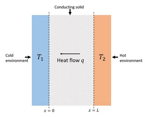
Thermal conductivity is a measure of a material’s ability to conduct heat. It is defined as the rate of heat transfer through a material per unit thickness per unit temperature difference. In other words, it quantifies how well a substance can transfer heat from one point to another.
In printed wiring boards (PWBs), also known as printed circuit boards (PCBs), thermal conductivity plays a critical role in the overall performance and reliability of the board. PWBs are used to mechanically support and electrically connect electronic components using conductive tracks, pads, and other features etched from one or more copper layers laminated onto a non-conductive substrate.
As electronic devices become smaller, faster, and more powerful, the amount of heat generated by the components on a PWB increases. If this heat is not effectively dissipated, it can lead to a variety of problems, including:
- Reduced performance and efficiency of the electronic components
- Shortened lifespan of the components and the overall device
- Damage to the PWB itself, such as delamination or warping
- Safety hazards, such as overheating or even fire
Therefore, it is essential for PWB designers and manufacturers to understand the thermal conductivity of the materials used in their boards and to design the board in a way that maximizes heat dissipation. By doing so, they can ensure the optimal performance, reliability, and safety of the end product.
Factors Affecting Thermal Conductivity in PWBs
Several factors can impact the thermal conductivity of a PWB, including:
Material Properties
The thermal conductivity of a PWB is largely determined by the properties of the materials used in its construction. The most common materials used in PWBs are:
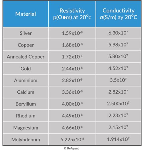
- Copper: Used for the conductive layers and features of the board. Copper has a high thermal conductivity of around 400 W/mK.
- FR-4: A composite material made of woven fiberglass cloth and an epoxy resin binder. It is the most widely used substrate material for PWBs. FR-4 has a relatively low thermal conductivity of around 0.3 W/mK.
- Solder mask: A thin layer of polymer applied over the copper traces to protect them from oxidation and prevent solder bridges. Solder mask typically has a low thermal conductivity, similar to FR-4.
- Solder: Used to attach components to the PWB. The thermal conductivity of solder varies depending on its composition but is generally lower than that of copper.
Other materials, such as aluminum, ceramics, or Thermal Interface materials (TIMs), may also be used in PWBs to enhance thermal conductivity.
Board Thickness
The thickness of a PWB can also affect its thermal conductivity. In general, thicker boards will have a higher thermal resistance (the inverse of conductivity) than thinner boards, assuming the same material composition. This is because heat has to travel a longer distance through the thickness of the board.
However, thicker boards also have more volume for heat to dissipate through, which can counteract the increased thermal resistance. The optimal board thickness will depend on the specific application and design constraints.
Copper Thickness and Coverage
The thickness and coverage of the copper layers in a PWB can have a significant impact on its thermal conductivity. Thicker copper layers will have a lower thermal resistance and can conduct heat more efficiently. Similarly, a higher percentage of copper coverage on the board will provide more pathways for heat to dissipate.
However, increasing copper thickness and coverage also increases the weight and cost of the board, so designers must balance thermal performance with other design constraints.
Thermal Vias
Thermal vias are small, plated holes drilled through a PWB to provide a conductive path for heat to flow from one layer to another. They are often used to transfer heat from high-power components on the surface of the board to the inner layers or to a heatsink on the opposite side of the board.
The effectiveness of thermal vias depends on several factors, including their size, spacing, and plating thickness. In general, more vias, larger vias, and thicker plating will all enhance thermal conductivity.

Measuring Thermal Conductivity in PWBs
There are several methods for measuring the thermal conductivity of a PWB, each with its own advantages and limitations. Some common methods include:
Guarded Hot Plate Method (ASTM C177)
The guarded hot plate method is a standard test method for measuring the thermal conductivity of flat, homogeneous materials. It involves placing a sample between two temperature-controlled plates and measuring the heat flow through the sample under steady-state conditions.
While this method is highly accurate and repeatable, it requires a relatively large, flat sample and can be time-consuming to set up and run.
Laser Flash Method (ASTM E1461)
The laser flash method is a rapid, non-destructive technique for measuring the thermal diffusivity of a material. It involves heating one side of a small sample with a short pulse of energy (usually from a laser) and measuring the temperature rise on the opposite side of the sample over time.
Thermal conductivity can then be calculated from the thermal diffusivity, specific heat capacity, and density of the material. This method is well-suited for small, thin samples like PWBs but may not be as accurate as other methods.
Heat Flow Meter Method (ASTM C518)
The heat flow meter method is similar to the guarded hot plate method but uses heat flux sensors to directly measure the heat flow through a sample instead of relying on temperature measurements alone. This allows for faster, more automated testing but may be less accurate than the guarded hot plate method.
Transient Plane Source Method (ISO 22007-2)
The transient plane source (TPS) method is a versatile technique that can measure the thermal conductivity, thermal diffusivity, and specific heat capacity of a material simultaneously. It involves applying a short electrical pulse to a flat sensor sandwiched between two pieces of the sample material and measuring the temperature response over time.
The TPS method is relatively fast and can accommodate small or irregularly shaped samples but requires good thermal contact between the sensor and sample.

Calculating Thermal Conductivity in PWBs
Once the thermal conductivity of a PWB has been measured using one of the methods described above, it can be used to calculate the thermal performance of the board under different operating conditions. Some common calculations include:
Thermal Resistance
Thermal resistance is a measure of a material’s ability to resist heat flow. It is the inverse of thermal conductivity and is defined as the temperature difference between two points divided by the heat flow between them:
$$R = \frac{\Delta T}{Q}$$
where $R$ is the thermal resistance (in K/W), $\Delta T$ is the temperature difference (in K), and $Q$ is the heat flow (in W).
For a PWB, the thermal resistance can be calculated using the board’s thickness ($t$), area ($A$), and thermal conductivity ($k$):
$$R = \frac{t}{k \cdot A}$$
A lower thermal resistance indicates better heat dissipation and is generally desirable for PWBs.
Junction-to-Ambient Thermal Resistance
The junction-to-ambient thermal resistance ($R_{ja}$) is a measure of how well a PWB can dissipate heat from a component (such as a microprocessor) to the surrounding environment. It includes the thermal resistance of the component package, the PWB, and any heatsinks or other cooling solutions.
$R_{ja}$ can be calculated using the following equation:
$$R_{ja} = \frac{T_j – T_a}{P}$$
where $T_j$ is the junction temperature of the component (in °C), $T_a$ is the ambient temperature (in °C), and $P$ is the power dissipated by the component (in W).
A lower $R_{ja}$ indicates better overall thermal performance and can be achieved by optimizing the thermal conductivity of the PWB, using thermal vias, or adding heatsinks or other cooling solutions.
Temperature Rise
The temperature rise of a component on a PWB can be calculated using the junction-to-ambient thermal resistance and the power dissipated by the component:
$$\Delta T = R_{ja} \cdot P$$
where $\Delta T$ is the temperature rise above ambient (in °C), $R_{ja}$ is the junction-to-ambient thermal resistance (in °C/W), and $P$ is the power dissipated by the component (in W).
Keeping the temperature rise within acceptable limits is critical for ensuring the reliability and performance of electronic components. PWB designers can use this calculation to verify that their board can adequately dissipate heat under worst-case operating conditions.

Design Considerations for Optimizing Thermal Conductivity in PWBs
When designing a PWB for optimal thermal performance, there are several key considerations to keep in mind:
Material Selection
Choosing materials with high thermal conductivity, such as copper or aluminum, can significantly improve the heat dissipation of a PWB. However, designers must also consider other material properties, such as electrical conductivity, dielectric constant, and mechanical strength, as well as cost and availability.
Board Stackup
The arrangement of layers in a PWB, known as the stackup, can have a significant impact on its thermal performance. Placing high-power components on the outer layers of the board, close to the surface, can facilitate heat dissipation. Additionally, using thicker copper layers or adding dedicated thermal layers (such as metal core layers) can enhance thermal conductivity.
Thermal Vias
Incorporating thermal vias into the design of a PWB is one of the most effective ways to improve its thermal conductivity. By providing a low-resistance path for heat to flow from the surface of the board to the inner layers or to a heatsink, thermal vias can significantly reduce the junction-to-ambient thermal resistance.
When using thermal vias, designers should consider factors such as via size, spacing, and plating thickness, as well as the placement of vias relative to high-power components.
Component Placement
The placement of components on a PWB can also affect its thermal performance. High-power components should be placed away from other heat-sensitive components and should be oriented to maximize heat dissipation (e.g., with the largest surface area facing outward).
Designers should also consider the airflow around the board and place components in a way that does not obstruct cooling air.
Heatsinks and Cooling Solutions
In some cases, the thermal conductivity of the PWB itself may not be sufficient to dissipate the heat generated by high-power components. In these situations, additional cooling solutions, such as heatsinks, fans, or liquid cooling systems, may be necessary.
When using heatsinks, it is important to select a material with high thermal conductivity (such as aluminum or copper) and to ensure good thermal contact between the heatsink and the component or board. Thermal interface materials (TIMs), such as thermal grease or thermal pads, can be used to improve this contact.
Conclusion
Thermal management is a critical aspect of PWB design, and understanding how to calculate and optimize the thermal conductivity of a board is essential for ensuring the performance, reliability, and safety of electronic devices.
By considering factors such as material properties, board thickness, copper coverage, and thermal vias, designers can create PWBs that effectively dissipate heat and maintain acceptable operating temperatures.
Furthermore, by using appropriate measurement techniques and calculations, such as thermal resistance and junction-to-ambient thermal resistance, designers can predict the thermal performance of a PWB and verify that it meets the requirements of the application.
As electronic devices continue to become more powerful and compact, the importance of thermal management in PWBs will only continue to grow. By staying up-to-date with the latest materials, design techniques, and analysis methods, PWB designers can ensure that their boards are able to keep up with the demands of the industry.
Frequently Asked Questions (FAQ)
What is the difference between thermal conductivity and thermal resistance?
Thermal conductivity is a material property that describes how well a substance can conduct heat, while thermal resistance is a measure of how well a material or system resists heat flow. Thermal conductivity is the inverse of thermal resistance, and a higher thermal conductivity indicates a lower thermal resistance (and vice versa).
What is the most important factor affecting the thermal conductivity of a PWB?
The most important factor affecting the thermal conductivity of a PWB is the choice of materials, particularly the substrate material and the copper layers. Using materials with high thermal conductivity, such as FR-4 with a high glass transition temperature (Tg) or metal core substrates, can significantly improve the heat dissipation of the board.
How do thermal vias work, and how many should I use in my PWB design?
Thermal vias are small, plated holes drilled through a PWB to provide a conductive path for heat to flow from one layer to another. They work by allowing heat to bypass the low-thermal-conductivity substrate material and flow through the high-conductivity copper plating.
The number of thermal vias needed in a PWB design depends on factors such as the power dissipation of the components, the board thickness, and the desired thermal performance. As a general rule, more vias will provide better heat dissipation, but designers must also consider the impact on Signal integrity and manufacturing costs.
Can I use a heatsink with a PWB, and how do I choose the right one?
Yes, heatsinks can be used with PWBs to improve heat dissipation, particularly for high-power components. When choosing a heatsink, consider factors such as the thermal conductivity of the heatsink material (aluminum and copper are common choices), the surface area and fin design of the heatsink, and the thermal interface material (TIM) used to connect the heatsink to the component or board.
It is also important to ensure that the heatsink is properly sized for the power dissipation of the component and the available space within the device enclosure.
What is the best way to measure the thermal conductivity of a PWB?
The best way to measure the thermal conductivity of a PWB depends on the size and shape of the board, as well as the desired accuracy and repeatability of the measurement. For small, thin samples like PWBs, the laser flash method (ASTM E1461) or the transient plane source method (ISO 22007-2) are often used, as they can accommodate small samples and provide rapid, non-destructive measurements.
For larger or thicker samples, the guarded hot plate method (ASTM C177) or the heat flow meter method (ASTM C518) may be more appropriate, as they can provide highly accurate and repeatable results. Ultimately, the choice of measurement method should be based on the specific requirements of the application and the available testing equipment and expertise.
| Method | Standard | Sample Size | Accuracy | Speed |
|---|---|---|---|---|
| Guarded Hot Plate | ASTM C177 | Large, flat | High | Slow |
| Laser Flash | ASTM E1461 | Small, thin | Moderate | Fast |
| Heat Flow Meter | ASTM C518 | Large, flat | Moderate | Fast |
| Transient Plane Source | ISO 22007-2 | Small, irregular | High | Fast |
Table 1: Comparison of common methods for measuring thermal conductivity in PWBs.

No responses yet