Understanding the Relationship Between Pin Length and PCB Thickness
When designing or manufacturing printed circuit boards (PCBs) that utilize through hole components, it is crucial to consider the relationship between the length of the component pins and the thickness of the PCB. Proper selection of pin lengths and PCB thicknesses ensures reliable electrical connections, mechanical stability, and ease of assembly. In this article, we will delve into the factors that influence pin length and PCB thickness decisions and provide guidelines for optimal design and manufacturing.
Pin Length Considerations
The length of through hole component pins plays a significant role in the assembly process and the overall reliability of the PCB. Here are some key considerations when selecting pin lengths:
-
PCB Thickness: The pin length must be sufficient to pass through the entire thickness of the PCB and protrude enough to allow for soldering. A general rule of thumb is to have the pin protrude at least 1.5 times the diameter of the pin or 0.5mm, whichever is greater.
-
Soldering Method: The choice of soldering method, such as Wave Soldering or hand soldering, can influence the required pin length. Wave soldering typically requires longer pins to ensure proper contact with the solder wave, while hand soldering can accommodate shorter pins.
-
Component Placement: The placement of components on the PCB can affect pin length requirements. If components are placed close to the edge of the board, longer pins may be necessary to provide enough clearance for soldering and inspection.
-
Mechanical Stability: Longer pins can provide better mechanical stability for components, especially for those subjected to vibration or mechanical stress. However, excessively long pins can increase the risk of bent or damaged pins during handling and assembly.
PCB Thickness Considerations
The thickness of the PCB is another critical factor that influences the selection of through hole component pin lengths. PCB thickness is determined by several factors, including:
-
Number of Layers: The number of copper layers in the PCB directly affects its thickness. Each additional layer adds to the overall thickness of the board.
-
Copper Thickness: The thickness of the copper traces on each layer contributes to the overall PCB thickness. Thicker copper traces are often used for high-current or high-power applications.
-
Insulation Thickness: The thickness of the insulation material between layers, typically FR-4 laminate, also impacts the total PCB thickness.
-
Application Requirements: The specific requirements of the application, such as mechanical strength, thermal management, and high-frequency performance, can dictate the necessary PCB thickness.
The table below provides a general guideline for selecting PCB thicknesses based on the number of layers:
| Number of Layers | Typical PCB Thickness |
|---|---|
| 1 – 2 | 0.8mm – 1.6mm |
| 4 | 1.6mm – 2.4mm |
| 6 | 2.4mm – 3.2mm |
| 8 or more | 3.2mm and above |
Determining Optimal Pin Length
To determine the optimal pin length for a given PCB thickness, consider the following guidelines:
-
Minimum Pin Protrusion: Ensure that the pins protrude at least 1.5 times the diameter of the pin or 0.5mm, whichever is greater, beyond the bottom side of the PCB. This allows for sufficient space for soldering and inspection.
-
Maximum Pin Protrusion: Avoid excessive pin protrusion, as it can increase the risk of bent or damaged pins during handling and assembly. A maximum protrusion of 2.5mm to 3mm is generally recommended.
-
Component Clearance: Consider the clearance required for components on both sides of the PCB. Ensure that the pin length allows for proper clearance between components and the PCB surface.
-
Soldering Method: If wave soldering is used, additional pin length may be necessary to ensure proper contact with the solder wave. Consult the specifications of the wave soldering equipment and process to determine the appropriate pin length.
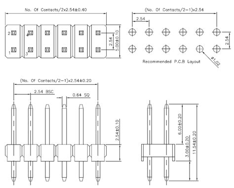
The table below provides a general recommendation for pin lengths based on PCB thickness:
| PCB Thickness | Recommended Pin Length |
|---|---|
| 0.8mm – 1.6mm | 3mm – 4mm |
| 1.6mm – 2.4mm | 4mm – 6mm |
| 2.4mm – 3.2mm | 6mm – 8mm |
| 3.2mm and above | 8mm and above |
Manufacturing Considerations
When manufacturing PCBs with through hole components, several factors should be considered to ensure optimal results:
-
Drilling Accuracy: Ensure that the drilling process for through holes is accurate and consistent. Misaligned or oversized holes can lead to poor component fit and soldering issues.
-
Plating Thickness: The plating thickness of the through holes should be sufficient to provide a reliable electrical connection and mechanical strength. Typically, a copper plating thickness of 25-35 microns is recommended.
-
Solder Mask Clearance: Provide adequate solder mask clearance around the through holes to prevent solder mask from interfering with the soldering process. A clearance of 0.1mm to 0.15mm is generally recommended.
-
Inspection and Quality Control: Implement robust inspection and quality control processes to ensure that the manufactured PCBs meet the specified pin length and PCB thickness requirements. Visual inspection, cross-sectional analysis, and electrical testing can help identify any issues.
Frequently Asked Questions (FAQ)
-
What happens if the pin length is too short for the PCB thickness?
If the pin length is too short, it may not protrude sufficiently from the bottom side of the PCB, making it difficult or impossible to solder properly. This can lead to poor electrical connections and reduced mechanical stability. -
Can I use longer pins than recommended for a given PCB thickness?
While using longer pins is possible, it is generally not recommended. Excessively long pins can increase the risk of bent or damaged pins during handling and assembly, and they may also interfere with other components on the PCB. -
How does the choice of soldering method affect pin length requirements?
Wave soldering typically requires longer pins to ensure proper contact with the solder wave, while hand soldering can accommodate shorter pins. It’s important to consider the specific requirements of the soldering method when selecting pin lengths. -
What should I do if I have components with different pin lengths on the same PCB?
If components with different pin lengths are used on the same PCB, it’s important to ensure that the PCB thickness accommodates the longest pins. Additionally, consider the placement of components to ensure proper clearance and accessibility for soldering. -
Can I modify the pin lengths of through hole components?
In some cases, it may be possible to modify the pin lengths of through hole components by trimming or extending them. However, this should be done carefully and only when necessary, as it can affect the component’s performance and reliability. It’s always best to select components with appropriate pin lengths for the specific PCB thickness and design requirements.
Conclusion
Selecting the appropriate pin lengths for through hole components based on PCB thickness is crucial for ensuring reliable electrical connections, mechanical stability, and ease of assembly. By considering factors such as PCB thickness, soldering method, component placement, and manufacturing processes, designers and manufacturers can make informed decisions and optimize their PCB Designs.
Remember to follow the guidelines for minimum and maximum pin protrusion, consider component clearances, and adhere to manufacturing best practices to achieve the best results. By understanding the relationship between pin length and PCB thickness, you can create high-quality, reliable PCBs that meet the specific requirements of your application.
No responses yet