Introduction to PCB Heat Dissipation
Printed Circuit Boards (PCBs) are essential components in modern electronic devices. They provide a platform for mounting and interconnecting electronic components, enabling complex circuits to be built in a compact and efficient manner. However, as electronic devices become more powerful and miniaturized, the heat generated by the components on the PCB can become a significant problem. If not properly managed, excessive heat can lead to component failure, reduced performance, and even damage to the PCB itself. This is where PCB heat dissipation comes into play.
PCB heat dissipation refers to the process of removing heat from the PCB and its components, ensuring that they operate within their specified temperature ranges. Effective heat dissipation is crucial for maintaining the reliability, longevity, and performance of electronic devices. In this article, we will explore the various methods and techniques used for PCB heat dissipation, including heat sinks, thermal vias, copper pours, and more.
The Importance of PCB Heat Dissipation
Before diving into the specific methods of PCB heat dissipation, let’s take a closer look at why it is so important. Electronic components generate heat as a byproduct of their operation. This heat, if not dissipated effectively, can lead to several problems:
-
Component Failure: Excessive heat can cause components to fail prematurely. High temperatures can accelerate the degradation of materials, leading to reduced lifespan and reliability.
-
Reduced Performance: As components heat up, their electrical characteristics can change, resulting in reduced performance. For example, a microprocessor may throttle its clock speed to prevent overheating, leading to slower operation.
-
PCB Damage: Prolonged exposure to high temperatures can cause the PCB itself to degrade. The copper traces on the PCB can expand and contract, leading to cracks and delamination. The PCB substrate material can also deteriorate, compromising its structural integrity.
-
Safety Concerns: In extreme cases, excessive heat can pose safety risks. Overheated components can potentially cause fires or burns, especially if they are in close proximity to flammable materials.
Given these potential consequences, it is clear that effective PCB heat dissipation is essential for ensuring the proper functioning and longevity of electronic devices.

Methods of PCB Heat Dissipation
There are several methods and techniques used for PCB heat dissipation. Each method has its own advantages and considerations, and the choice of method depends on factors such as the amount of heat generated, the available space, and the cost constraints. Let’s explore some of the most common methods:
Heat Sinks
Heat sinks are one of the most widely used methods for PCB heat dissipation. A heat sink is a passive cooling device that is attached to a heat-generating component, such as a microprocessor or power transistor. The heat sink absorbs the heat from the component and dissipates it into the surrounding air through its large surface area.
Heat sinks come in various shapes and sizes, ranging from small clip-on designs to large extruded aluminum profiles. They are typically made of materials with high thermal conductivity, such as aluminum or copper, to facilitate efficient heat transfer.
When selecting a heat sink for a PCB, several factors need to be considered:
-
Thermal Resistance: The thermal resistance of a heat sink determines how effectively it can dissipate heat. A lower thermal resistance indicates better cooling performance.
-
Surface Area: A larger surface area allows for more heat dissipation. Heat sinks with fins or other protrusions increase the surface area and improve cooling efficiency.
-
Mounting Method: Heat sinks can be attached to components using various methods, such as adhesive tape, clips, or screws. The mounting method should provide good thermal contact between the heat sink and the component.
-
Airflow: Heat sinks rely on airflow to carry away the dissipated heat. Adequate airflow around the heat sink is necessary for optimal cooling performance.
| Heat Sink Type | Thermal Resistance (°C/W) | Surface Area (cm²) | Mounting Method |
|---|---|---|---|
| Clip-on | 5-10 | 10-50 | Clip |
| Extruded | 1-5 | 50-500 | Screw or Adhesive |
| Forged | 0.5-2 | 100-1000 | Screw or Solder |
Thermal Vias
Thermal vias are another effective method for PCB heat dissipation. A via is a small hole drilled through the PCB that allows heat to be transferred from one layer to another. Thermal vias are specifically designed to provide a low-resistance thermal path from a heat-generating component to a heat-dissipating layer, such as a Ground Plane or a heat sink.
Thermal vias are typically placed directly underneath or around the heat-generating component. They are filled with a thermally conductive material, such as copper or a specialized thermal compound, to enhance heat transfer.
When designing thermal vias, several factors need to be considered:
-
Via Size: Larger vias have lower thermal resistance and can transfer heat more effectively. However, larger vias also consume more board space.
-
Via Pitch: The spacing between vias, known as the via pitch, affects the overall thermal conductivity. A tighter pitch allows for more vias to be placed, improving heat transfer.
-
Via Fill Material: The choice of via fill material impacts the thermal conductivity. Copper-filled vias provide the best thermal performance but are more expensive than thermal compound-filled vias.
| Via Size (mm) | Thermal Resistance (°C/W) | Via Pitch (mm) | Fill Material |
|---|---|---|---|
| 0.3 | 50-100 | 1.0-1.5 | Copper |
| 0.5 | 20-50 | 1.5-2.0 | Thermal Compound |
| 0.8 | 10-20 | 2.0-2.5 | Copper |
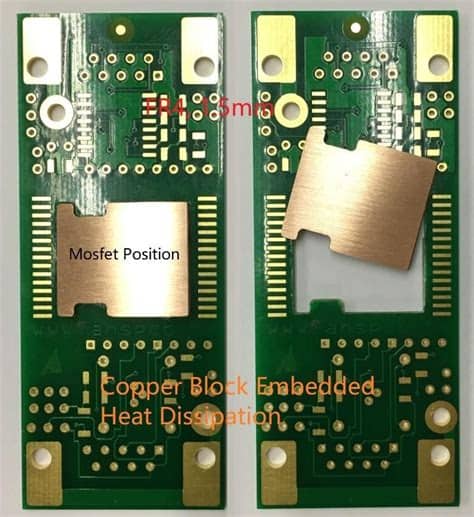
Copper Pours
Copper pours, also known as copper fills or copper planes, are large areas of copper on the PCB that are used for heat dissipation. By utilizing the unused areas of the PCB for copper pours, the overall thermal conductivity of the board can be improved.
Copper pours are typically placed on the outer layers of the PCB, as they have direct exposure to the surrounding air. They can be connected to heat-generating components through thermal vias or directly to the component’s thermal pad.
When designing copper pours, consider the following:
-
Copper Thickness: Thicker copper pours have lower thermal resistance and can dissipate more heat. However, thicker copper also increases the overall weight and cost of the PCB.
-
Copper Coverage: The extent of copper coverage on the PCB affects the heat dissipation capabilities. A larger copper pour area provides more surface area for heat dissipation.
-
Thermal Relief: Thermal relief patterns, such as spoke-style or cross-style, are used to connect copper pours to component pads while minimizing thermal stress during soldering.
| Copper Thickness (oz) | Thermal Conductivity (W/mK) | Copper Coverage (%) |
|---|---|---|
| 1 | 380 | 30-50 |
| 2 | 380 | 50-70 |
| 3 | 380 | 70-90 |
Thermal Interface Materials
Thermal interface materials (TIMs) are substances that are applied between a heat-generating component and a heat sink or other cooling solution to enhance thermal conductivity. TIMs fill the microscopic air gaps and irregularities between the surfaces, allowing for more efficient heat transfer.
Common types of TIMs include:
-
Thermal Grease: Thermal grease, also known as thermal paste, is a viscous substance that is applied between the component and the heat sink. It is composed of thermally conductive particles suspended in a silicone or hydrocarbon base.
-
Thermal Pads: Thermal pads are pre-cut, thermally conductive sheets that are placed between the component and the heat sink. They are made of materials such as silicone or graphite and provide a convenient and mess-free alternative to thermal grease.
-
Phase Change Materials: Phase change materials (PCMs) are substances that change phase (e.g., from solid to liquid) at a specific temperature. They are applied between the component and the heat sink and provide excellent thermal conductivity due to their conformability and gap-filling properties.
| TIM Type | Thermal Conductivity (W/mK) | Application Method |
|---|---|---|
| Thermal Grease | 2-8 | Manual |
| Thermal Pad | 1-5 | Pre-cut |
| Phase Change Material | 5-10 | Manual or Pre-applied |

PCB Design Considerations for Heat Dissipation
In addition to the specific methods of heat dissipation, there are several PCB design considerations that can impact the overall thermal performance of the board. By taking these factors into account during the design phase, engineers can optimize the PCB for effective heat dissipation.
Component Placement
The placement of components on the PCB plays a significant role in heat dissipation. Heat-generating components should be placed strategically to minimize thermal interaction and maximize cooling efficiency. Consider the following guidelines:
-
Spacing: Provide adequate spacing between heat-generating components to prevent thermal coupling and allow for better airflow.
-
Orientation: Orient components in a way that promotes natural convection and facilitates heat dissipation. For example, placing components vertically can improve airflow compared to horizontal placement.
-
Proximity to Cooling Solutions: Place heat-generating components close to cooling solutions, such as heat sinks or thermal vias, to minimize the thermal path and improve heat transfer.
Layer Stack-up
The layer stack-up of the PCB can also impact heat dissipation. Consider the following aspects:
-
Thermal Conductivity: Use PCB materials with high thermal conductivity, such as copper or aluminum-backed substrates, to facilitate heat transfer through the layers.
-
Dielectric Thickness: Minimize the thickness of the dielectric layers between copper layers to reduce thermal resistance. Thinner dielectrics allow for better heat conduction.
-
Copper Weight: Use appropriate copper weights for the layers involved in heat dissipation. Thicker copper layers have lower thermal resistance and can dissipate more heat.
Airflow and Ventilation
Adequate airflow and ventilation are crucial for effective heat dissipation. Consider the following factors:
-
Enclosure Design: Design the enclosure or housing of the electronic device to allow for sufficient airflow around the PCB. Incorporate vents or openings to facilitate air circulation.
-
Fan Placement: If using active cooling solutions like fans, position them strategically to direct airflow over heat-generating components and heat sinks.
-
Airflow Obstructions: Avoid placing components or structures that obstruct airflow around heat-generating components. Ensure that there is a clear path for air to flow and carry away the dissipated heat.

Thermal Simulation and Testing
To ensure that the PCB design and heat dissipation methods are effective, thermal simulation and testing are essential. Thermal simulation software allows engineers to analyze the thermal behavior of the PCB and identify potential hot spots or areas of concern. These simulations can help optimize component placement, heat sink selection, and other design parameters.
Once the PCB is fabricated, thermal testing should be conducted to validate the simulation results and ensure that the actual thermal performance meets the design requirements. Thermal testing can involve techniques such as thermocouples, infrared imaging, or thermal test chips to measure the temperature at various points on the PCB.
Based on the simulation and testing results, design modifications may be necessary to improve heat dissipation and ensure that the PCB operates within the specified temperature range.
Frequently Asked Questions (FAQ)
-
What is the purpose of PCB heat dissipation?
PCB heat dissipation aims to remove heat generated by electronic components on the PCB, preventing overheating and ensuring reliable operation. -
What are the consequences of insufficient PCB heat dissipation?
Insufficient PCB heat dissipation can lead to component failure, reduced performance, PCB damage, and potential safety risks such as fires or burns. -
What are some common methods used for PCB heat dissipation?
Common methods for PCB heat dissipation include heat sinks, thermal vias, copper pours, and thermal interface materials. -
How do heat sinks work in PCB heat dissipation?
Heat sinks are attached to heat-generating components and dissipate heat into the surrounding air through their large surface area, helping to cool the components. -
What are thermal vias, and how do they contribute to PCB heat dissipation?
Thermal vias are small holes drilled through the PCB that provide a low-resistance thermal path from heat-generating components to heat-dissipating layers, allowing heat to be transferred more efficiently.
Conclusion
PCB heat dissipation is a critical aspect of Electronic design that ensures the reliability, performance, and longevity of electronic devices. By understanding the importance of heat dissipation and implementing appropriate methods such as heat sinks, thermal vias, copper pours, and thermal interface materials, engineers can effectively manage the thermal challenges associated with PCBs.
Furthermore, considering PCB Design Factors such as component placement, layer stack-up, and airflow/ventilation can further optimize the thermal performance of the board. Thermal simulation and testing are essential tools for validating the effectiveness of the chosen heat dissipation methods and identifying areas for improvement.
As electronic devices continue to become more powerful and compact, the importance of effective PCB heat dissipation will only continue to grow. By staying informed about the latest techniques and best practices in PCB thermal management, engineers can design robust and reliable electronic systems that can withstand the challenges of heat generation.
No responses yet