Understanding the Importance of Thermal-PCB-REsistance
Printed Circuit Boards (PCBs) are essential components in modern electronic devices, serving as the foundation for interconnecting various electronic components. One crucial aspect of PCB design is managing the thermal behavior of the board, which is quantified by its thermal resistance. Thermal-PCB-Resistance plays a vital role in ensuring the reliability, performance, and longevity of electronic systems.
What is Thermal Resistance?
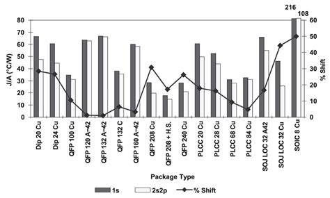
Thermal resistance is a measure of a material’s ability to resist heat flow. In the context of PCBs, thermal resistance refers to the board’s ability to dissipate heat generated by the electronic components mounted on it. The lower the thermal resistance, the better the PCB’s ability to transfer heat away from the components and into the surrounding environment.
Thermal resistance is expressed in units of degrees Celsius per watt (°C/W) or Kelvin per watt (K/W). It is defined as the temperature difference between two points on the PCB divided by the amount of heat flowing between those points.
Factors Affecting Thermal-PCB-Resistance
Several factors contribute to the thermal resistance of a PCB:
-
PCB Material: The choice of PCB material significantly impacts its thermal resistance. Common PCB materials include FR-4, polyimide, and metal-core PCBs (MCPCBs). Each material has different thermal conductivity properties, with MCPCBs offering the lowest thermal resistance.
-
PCB Thickness: Thicker PCBs generally have lower thermal resistance compared to thinner ones. This is because a thicker board provides more cross-sectional area for heat to flow through, reducing the overall thermal resistance.
-
Copper Thickness: The thickness of the copper traces on the PCB also affects its thermal resistance. Thicker copper traces have lower electrical resistance and can carry more current, which helps in distributing heat more efficiently across the board.
-
Thermal Vias: Thermal vias are small holes drilled through the PCB that are filled with conductive material, typically copper. They provide a low-resistance path for heat to flow from one side of the board to the other, helping to dissipate heat more effectively.
-
Component Placement: The placement of components on the PCB can impact its thermal resistance. Components that generate significant heat should be placed strategically to allow for optimal heat dissipation. Proper spacing between components and the use of thermal management techniques, such as heatsinks or thermal pads, can help reduce thermal resistance.
Measuring Thermal-PCB-Resistance
Measuring the thermal resistance of a PCB is crucial for ensuring its proper functioning and reliability. There are several methods for measuring thermal resistance:
-
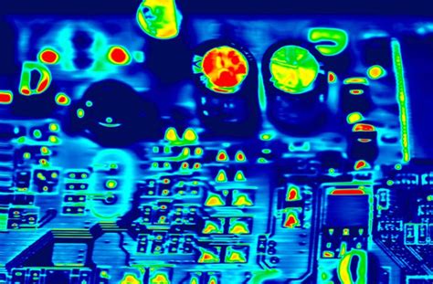
Thermal Imaging: Thermal imaging cameras can be used to visualize the temperature distribution across the PCB. By analyzing the thermal images, engineers can identify hot spots and areas of high thermal resistance.
-
Thermocouples: Thermocouples are temperature sensors that can be attached to specific points on the PCB to measure the temperature at those locations. By comparing the temperatures at different points, the thermal resistance can be calculated.
-
Thermal Simulation: Thermal simulation software can be used to model the thermal behavior of a PCB. These simulations take into account the PCB material, component placement, and other factors to predict the thermal resistance and identify potential thermal issues.
Thermal Management Techniques
To mitigate the effects of thermal resistance and ensure proper heat dissipation, several thermal management techniques can be employed:
-
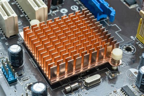
Heatsinks: Heatsinks are metallic structures attached to components that generate significant heat. They increase the surface area available for heat dissipation and help in transferring heat away from the component.
-
Thermal Interface Materials (TIMs): TIMs, such as thermal pads or thermal pastes, are used to fill the gaps between components and heatsinks. They improve the thermal contact and facilitate better heat transfer.
-
Forced Air Cooling: Fans or blowers can be used to actively circulate air over the PCB, enhancing convective heat transfer and reducing the overall thermal resistance.
-
Liquid Cooling: In high-power applications, liquid cooling systems can be employed to efficiently remove heat from the PCB. Liquid coolants have higher thermal conductivity compared to air, allowing for more effective heat dissipation.
-
PCB Design Optimization: Optimizing the PCB layout and component placement can help in reducing thermal resistance. This includes proper spacing between components, using wider traces for high-current paths, and incorporating thermal vias strategically.
The Impact of Thermal-PCB-Resistance on Electronic Systems
Reliability and Longevity
Thermal-PCB-Resistance has a direct impact on the reliability and longevity of electronic systems. When components operate at high temperatures due to inadequate heat dissipation, they are subjected to increased stress and can experience accelerated aging. This can lead to premature failures and reduced overall system reliability.
Electronic components have specified maximum operating temperatures, and exceeding these limits can cause permanent damage. Proper thermal management, achieved through low thermal resistance, helps in keeping component temperatures within safe operating ranges, extending their lifespan.
Performance and Efficiency
High thermal resistance can also affect the performance and efficiency of electronic systems. As components heat up, their electrical characteristics may change, leading to degraded performance. For example, high temperatures can increase the resistance of conductors, resulting in increased power loss and reduced efficiency.
In power electronics applications, such as switching regulators or power amplifiers, thermal management is critical. Excessive heat can cause power devices to operate less efficiently, leading to increased power dissipation and reduced overall system efficiency.
Safety Considerations
Thermal-PCB-Resistance also plays a role in ensuring the safety of electronic systems. Overheating can pose risks such as fire hazards or burns to users. Proper thermal management helps in preventing such safety issues by maintaining component temperatures within safe limits.
In applications where the PCB is exposed to harsh environmental conditions, such as high ambient temperatures or limited airflow, thermal resistance becomes even more critical. Adequate heat dissipation is necessary to prevent overheating and ensure safe operation under these challenging conditions.

Designing for Optimal Thermal-PCB-Resistance
Material Selection
Selecting the appropriate PCB material is crucial for achieving optimal thermal resistance. The choice of material depends on various factors, including the operating temperature range, power dissipation requirements, and cost considerations.
| Material | Thermal Conductivity (W/mK) | Advantages | Disadvantages |
|---|---|---|---|
| FR-4 | 0.3 – 0.4 | Low cost, widely available | Poor thermal conductivity |
| Polyimide | 0.2 – 0.3 | High temperature stability, good electrical properties | Expensive, limited thermal conductivity |
| Metal-Core PCB | 1.0 – 8.0 | Excellent thermal conductivity, high power handling | Higher cost, limited flexibility |
| Ceramic PCB | 20 – 200 | High thermal conductivity, excellent stability | Expensive, brittle, limited availability |
Metal-core PCBs (MCPCBs) are often preferred for high-power applications due to their excellent thermal conductivity. They consist of a metal substrate, typically aluminum, with a thin dielectric layer and copper traces on top. The metal substrate acts as a heatsink, efficiently spreading and dissipating heat from the components.
Thermal Vias and Copper Thickness
Incorporating thermal vias and using appropriate copper thickness are effective strategies for reducing thermal resistance. Thermal vias provide a low-resistance path for heat to flow through the PCB, allowing for better heat dissipation.
When designing thermal vias, consider the following guidelines:
– Place thermal vias as close to the heat-generating components as possible.
– Use a sufficient number of thermal vias to provide adequate heat transfer.
– Ensure proper spacing between thermal vias to avoid compromising the PCB’s structural integrity.
– Consider using filled thermal vias, such as copper-filled or conductive epoxy-filled vias, for enhanced thermal performance.
Increasing the copper thickness of the PCB traces can also help in reducing thermal resistance. Thicker copper traces have lower electrical resistance and can carry more current, aiding in heat distribution. However, increasing copper thickness also impacts the manufacturing cost and PCB weight.
Component Placement and Spacing
Proper component placement and spacing are essential for optimizing thermal-PCB-resistance. When placing components on the PCB, consider the following guidelines:
– Position heat-generating components away from thermally sensitive components to avoid heat transfer between them.
– Provide adequate spacing between components to allow for proper airflow and heat dissipation.
– Place components strategically to leverage natural convection currents for enhanced cooling.
– Consider the use of thermal management techniques, such as heatsinks or thermal pads, for components with high heat dissipation requirements.
Thermal Simulation and Analysis
Thermal simulation and analysis tools are valuable resources for optimizing PCB thermal design. These tools allow engineers to model the thermal behavior of the PCB and identify potential thermal issues before physical prototyping.
Thermal simulation software, such as ANSYS Icepak or Mentor Graphics FloTHERM, provides insights into temperature distribution, heat flow paths, and thermal resistance. By iterating through different design scenarios and evaluating the simulation results, engineers can make informed decisions to optimize the PCB’s thermal performance.
Thermal analysis should be performed early in the design process to identify and address thermal challenges proactively. It helps in avoiding costly design changes later in the development cycle and ensures the PCB meets the thermal requirements of the application.

Frequently Asked Questions (FAQ)
- What is the difference between thermal resistance and thermal conductivity?
- Thermal resistance is a measure of a material’s ability to resist heat flow, expressed in units of °C/W or K/W. It represents the temperature difference between two points divided by the heat flow between those points.
-
Thermal conductivity, on the other hand, is a material property that quantifies the ability of a material to conduct heat. It is expressed in units of W/mK and represents the rate of heat transfer through a material.
-
How does the PCB material affect thermal resistance?
- The choice of PCB material significantly impacts thermal resistance. Different materials have varying thermal conductivity properties.
- FR-4, a common PCB material, has relatively poor thermal conductivity, while metal-core PCBs (MCPCBs) offer excellent thermal conductivity due to their metal substrate.
-
Materials with higher thermal conductivity, such as MCPCBs or ceramic PCBs, are preferred for applications with high heat dissipation requirements.
-
What are thermal vias, and how do they help in reducing thermal resistance?
- Thermal vias are small holes drilled through the PCB that are filled with conductive material, typically copper.
- They provide a low-resistance path for heat to flow from one side of the board to the other, helping to dissipate heat more effectively.
-
Thermal vias are placed strategically near heat-generating components to transfer heat away from the components and into the surrounding environment.
-
How does component placement impact thermal-PCB-resistance?
- Proper component placement is crucial for optimizing thermal-PCB-resistance. Heat-generating components should be placed away from thermally sensitive components to avoid heat transfer between them.
- Adequate spacing should be provided between components to allow for proper airflow and heat dissipation.
-
Strategic placement of components can leverage natural convection currents for enhanced cooling.
-
What are some thermal management techniques used to mitigate the effects of thermal resistance?
- Heatsinks: Metallic structures attached to heat-generating components to increase the surface area available for heat dissipation.
- Thermal Interface Materials (TIMs): Materials such as thermal pads or pastes used to fill gaps between components and heatsinks, improving thermal contact and heat transfer.
- Forced Air Cooling: Fans or blowers used to actively circulate air over the PCB, enhancing convective heat transfer.
- Liquid Cooling: Liquid coolants with high thermal conductivity used to efficiently remove heat from the PCB in high-power applications.
- PCB Design Optimization: Optimizing PCB layout, component placement, and incorporating thermal vias strategically to reduce thermal resistance.

Conclusion
Thermal-PCB-Resistance plays a critical role in the performance, reliability, and safety of electronic systems. Understanding the factors that influence thermal resistance and employing appropriate design techniques are essential for achieving optimal thermal management.
By selecting suitable PCB materials, incorporating thermal vias and appropriate copper thickness, optimizing component placement, and utilizing thermal management techniques, designers can effectively reduce thermal resistance and ensure proper heat dissipation.
Thermal simulation and analysis tools provide valuable insights into the thermal behavior of PCBs, enabling engineers to make informed design decisions and optimize the thermal performance of their systems.
As electronic systems continue to advance in complexity and power density, the importance of thermal-PCB-resistance will only continue to grow. By prioritizing thermal considerations in PCB design, engineers can develop reliable, efficient, and safe electronic products that meet the ever-increasing demands of modern applications.

No responses yet