Introduction to the 1N4003 Diode
The 1N4003 is a popular general-purpose rectifier diode used in a wide range of electronic applications. It is part of the 1N400x series of diodes, which includes the 1N4001, 1N4002, 1N4004, 1N4005, 1N4006, and 1N4007. The 1N4003 diode is known for its reliability, affordability, and versatility, making it a go-to choice for many electronics enthusiasts, hobbyists, and professionals.
In this comprehensive guide, we’ll explore the features, specifications, and applications of the 1N4003 diode, as well as provide practical tips for using it in your projects.
What is a Diode?
Before diving into the specifics of the 1N4003 diode, let’s first understand what a diode is and how it works.
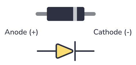
A diode is a two-terminal electronic component that allows current to flow in only one direction, from its anode to its cathode. When the voltage at the anode is higher than the voltage at the cathode, the diode is said to be forward-biased, and current flows through it. Conversely, when the voltage at the cathode is higher than the voltage at the anode, the diode is reverse-biased, and current flow is blocked.
Diodes are used in various applications, such as:
- Rectification: Converting alternating current (AC) to direct current (DC)
- Voltage regulation: Maintaining a constant voltage level
- Overvoltage protection: Preventing damage to sensitive components
- Logic gates: Implementing digital logic functions

1N4003 Diode Specifications
To effectively use the 1N4003 diode in your projects, it’s essential to understand its specifications. The following table summarizes the key specifications of the 1N4003 diode:
| Parameter | Value |
|---|---|
| Maximum Repetitive Peak Reverse Voltage (VRRM) | 200 V |
| Maximum RMS Voltage (VRMS) | 140 V |
| Maximum DC Blocking Voltage (VDC) | 200 V |
| Maximum Average Forward Rectified Current (IF(AV)) | 1 A |
| Peak Forward Surge Current (IFSM), 8.3 ms half sine-wave | 30 A |
| Maximum Instantaneous Forward Voltage (VF) at 1 A | 1.1 V |
| Maximum DC Reverse Current (IR) at rated VDC | 5 μA |
| Typical Junction Capacitance (Cj) at 4 V, 1 MHz | 15 pF |
| Operating and Storage Temperature Range (TJ, TSTG) | -65 to +175 °C |
Maximum Repetitive Peak Reverse Voltage (VRRM)
The Maximum Repetitive Peak Reverse Voltage (VRRM) is the maximum voltage that can be applied across the diode in the reverse direction without causing breakdown. For the 1N4003 diode, the VRRM is 200 V.
Maximum RMS Voltage (VRMS) and Maximum DC Blocking Voltage (VDC)
The Maximum RMS Voltage (VRMS) and Maximum DC Blocking Voltage (VDC) are related to the VRRM. The VRMS is the maximum root-mean-square (RMS) value of the AC voltage that can be applied across the diode, while the VDC is the maximum DC voltage that can be applied in the reverse direction. For the 1N4003 diode, the VRMS is 140 V, and the VDC is 200 V.
Maximum Average Forward Rectified Current (IF(AV))
The Maximum Average Forward Rectified Current (IF(AV)) is the maximum average current that can flow through the diode in the forward direction. For the 1N4003 diode, the IF(AV) is 1 A.
Peak Forward Surge Current (IFSM)
The Peak Forward Surge Current (IFSM) is the maximum current that the diode can withstand in the forward direction for a short duration, typically specified as an 8.3 ms half sine-wave pulse. For the 1N4003 diode, the IFSM is 30 A.
Maximum Instantaneous Forward Voltage (VF)
The Maximum Instantaneous Forward Voltage (VF) is the voltage drop across the diode when it is conducting in the forward direction at a specified current. For the 1N4003 diode, the VF is 1.1 V at a forward current of 1 A.
Maximum DC Reverse Current (IR)
The Maximum DC Reverse Current (IR) is the leakage current that flows through the diode when it is reverse-biased at the rated VDC. For the 1N4003 diode, the IR is 5 μA at the rated VDC.
Typical Junction Capacitance (Cj)
The Typical Junction Capacitance (Cj) is the capacitance of the diode’s p-n junction at a specified reverse voltage and frequency. For the 1N4003 diode, the Cj is typically 15 pF at 4 V and 1 MHz.
Operating and Storage Temperature Range (TJ, TSTG)
The Operating and Storage Temperature Range (TJ, TSTG) specifies the temperature limits within which the diode can operate and be stored without damage. For the 1N4003 diode, the TJ and TSTG range from -65 to +175 °C.

1N4003 Diode Features
The 1N4003 diode offers several features that make it a popular choice for various applications:
- Wide Voltage Range: With a VRRM of 200 V, the 1N4003 diode can handle a wide range of voltages, making it suitable for many applications.
- High Current Capability: The 1N4003 diode can handle an average forward current of 1 A and a peak forward surge current of 30 A, allowing it to be used in high-current applications.
- Low Forward Voltage Drop: The low forward voltage drop of 1.1 V at 1 A ensures minimal power loss when the diode is conducting.
- Fast Switching: The 1N4003 diode has a fast switching speed, making it suitable for high-frequency applications.
- Robust Construction: The diode’s construction ensures reliable operation and long-term stability.
Applications of the 1N4003 Diode
The 1N4003 diode finds use in a wide range of applications, including:
- Power Supply Rectification: The 1N4003 diode is commonly used in power supply circuits to convert AC to DC. It can be used in both half-wave and full-wave rectifier configurations.
- Reverse Polarity Protection: The diode can be used to protect sensitive electronic components from damage caused by accidentally reversing the power supply polarity.
- Flyback Diodes: In inductive load switching applications, such as relay drivers and Motor Controllers, the 1N4003 diode can be used as a flyback diode to suppress voltage spikes generated by the inductive load.
- Voltage Clamping: The diode can be used to clamp voltages to a specific level, protecting sensitive components from overvoltage conditions.
- Isolation: The 1N4003 diode can be used to isolate different sections of a circuit, preventing unwanted interactions between them.
Using the 1N4003 Diode in Your Projects
When using the 1N4003 diode in your projects, consider the following tips:
- Observe Polarity: Always ensure that the diode is connected with the correct polarity. The cathode is typically marked with a stripe on the diode’s body.
- Consider the Voltage and Current Ratings: Ensure that the diode’s voltage and current ratings are appropriate for your application. Exceeding these ratings can lead to diode failure and potential damage to other components.
- Use Appropriate Heat Sinking: When the diode is subjected to high currents, it may generate significant heat. Use appropriate heat sinking methods to dissipate this heat and prevent thermal damage to the diode and nearby components.
- Use Series Diodes for Higher Voltages: If your application requires handling voltages higher than the 1N4003’s VRRM, you can use multiple diodes in series to distribute the voltage stress across them.
- Consider the Diode’s Recovery Time: In high-frequency applications, the diode’s reverse recovery time can be a critical factor. Ensure that the 1N4003 diode’s recovery time is suitable for your application, or consider using a faster diode if needed.
Frequently Asked Questions (FAQ)
1. Can I use a 1N4003 diode instead of a 1N4001 or 1N4002?
Yes, you can use a 1N4003 diode in place of a 1N4001 or 1N4002 diode. The 1N4003 has a higher voltage rating, so it can handle the same applications as the 1N4001 and 1N4002, and more.
2. What is the difference between the 1N4003 and 1N4004 diodes?
The main difference between the 1N4003 and 1N4004 diodes is their voltage ratings. The 1N4003 has a VRRM of 200 V, while the 1N4004 has a VRRM of 400 V. If your application requires handling voltages higher than 200 V, you should use the 1N4004 or a higher-rated diode.
3. Can I use the 1N4003 diode for high-frequency applications?
The 1N4003 diode can be used in high-frequency applications, but its performance may be limited by its reverse recovery time. If your application demands very high frequencies or fast switching speeds, you may need to consider using a diode specifically designed for high-frequency operation, such as a Schottky diode.
4. How do I test a 1N4003 diode?
To test a 1N4003 diode, you can use a multimeter in the diode test mode. Connect the multimeter’s positive lead to the diode’s anode and the negative lead to the cathode. In the forward-biased condition, the multimeter should display a voltage drop of approximately 0.7 V. When the leads are reversed (reverse-biased condition), the multimeter should display an open circuit or a very high resistance.
5. What is the package type of the 1N4003 diode?
The 1N4003 diode is commonly available in the DO-41 (also known as DO-204AL) axial-lead package. This package consists of a cylindrical body with two leads extending from either end. The cathode lead is typically marked with a stripe or band on the diode’s body.
Conclusion
The 1N4003 diode is a versatile and reliable component that finds use in a wide range of electronic applications. Its high voltage rating, high current capability, and fast switching speed make it a popular choice for power supply rectification, reverse polarity protection, flyback diodes, voltage clamping, and isolation circuits.
By understanding the specifications, features, and proper usage guidelines of the 1N4003 diode, you can effectively incorporate it into your projects and designs. Always ensure that the diode is operating within its rated limits and is properly heat-sinked when necessary.
As with any electronic component, it’s essential to source the 1N4003 diode from reputable suppliers to ensure quality and reliability. When in doubt, consult the diode’s datasheet or seek guidance from experienced professionals.
With its robust construction and wide availability, the 1N4003 diode will continue to be a go-to choice for electronics enthusiasts, hobbyists, and professionals alike.
No responses yet