Introduction to Zener Diodes
Zener diodes are special types of diodes that are designed to operate in the reverse breakdown region. Unlike regular diodes that block current flow when reverse biased, Zener diodes will conduct a large current when the reverse voltage exceeds a certain threshold known as the Zener voltage (Vz). This property makes Zener diodes useful for voltage regulation, overvoltage protection, and voltage reference applications.
The Zener voltage is determined by the doping levels and geometry of the PN junction. Typical Zener diodes have breakdown voltages ranging from a few volts up to hundreds of volts. When operating in the Zener region, the voltage across the diode remains nearly constant even as the current varies over a wide range. This voltage regulating behavior is what allows Zener diodes to provide a stable reference voltage.
Key Characteristics of Zener Diodes
| Parameter | Description |
|---|---|
| Zener Voltage (Vz) | The reverse voltage at which the Zener diode begins to conduct heavily and regulate the voltage. |
| Zener Current (Iz) | The current that flows through the Zener diode when operating in the breakdown region. |
| Power Dissipation (Pd) | The maximum power the Zener diode can safely dissipate without damage. |
| Dynamic Resistance (Zz) | The small-signal resistance of the Zener diode when operating in the breakdown region. |
To ensure reliable operation, it is important to select a Zener diode with the appropriate voltage rating and power dissipation capability for the intended application. Exceeding the maximum ratings can cause the device to fail or degrade over time.
The Need for a Zener Diode Tester
When working with Zener diodes, it is often necessary to verify their functionality and measure key parameters such as the Zener voltage and dynamic resistance. A dedicated Zener diode tester can simplify this task and provide accurate results without the need for expensive test equipment.
Some common scenarios where a Zener diode tester is useful include:
- Sorting and matching Zener diodes for critical applications
- Troubleshooting voltage regulation circuits
- Verifying the performance of Zener diodes after exposure to stress or aging
- Characterizing the voltage and current characteristics of unmarked or unknown Zener diodes
By building a simple Zener diode tester, hobbyists and engineers can quickly assess the health and suitability of Zener diodes for their projects.
Circuit Design and Components
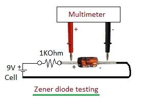
The Zener diode tester circuit consists of a adjustable voltage source, current limiting resistor, and a means to measure voltage and current. The basic schematic is shown below:
        +---------+
        |         |
       +-+        |
       | | R1     |
       | |        |
+------+-+----+   |
|      |      |   |
|     +---+  +---+
|     |   |  |
|     | D1|  | V
|     |   |  |
+-----+---+--+---+
      |      |
     GND    GND
The components required for the Zener diode tester are:
-
Adjustable DC voltage source (V1): This can be a variable bench power supply or a fixed voltage source with a potentiometer for adjustment. The voltage range should cover the expected Zener voltages of the diodes to be tested.
-
Current limiting resistor (R1): This resistor limits the current through the Zener diode to a safe value and allows for measuring the Zener current. The resistance value should be chosen based on the maximum expected Zener current and power dissipation of the diode under test. A typical value is a few hundred ohms to a few kilohms.
-
Zener diode under test (D1): This is the Zener diode being characterized or tested.
-
Voltmeter (V): A digital multimeter or oscilloscope can be used to measure the voltage across the Zener diode.
-
Ammeter (A): An ammeter or current sensing resistor can be used to measure the current through the Zener diode. Alternatively, the voltage across the current limiting resistor can be measured and the current calculated using Ohm’s law.
Selecting the Current Limiting Resistor
The value of the current limiting resistor (R1) should be chosen to ensure the Zener diode does not exceed its maximum power dissipation rating. The power dissipated by the Zener diode is given by:
Pd = Vz * Iz
Where Pd is the power dissipation, Vz is the Zener voltage, and Iz is the Zener current.
To limit the power dissipation, the maximum Zener current should be:
Iz_max = Pd_max / Vz
Where Pd_max is the maximum power dissipation rating of the Zener diode.
The value of the current limiting resistor can then be calculated using Ohm’s law:
R1 = (Vs - Vz) / Iz_max
Where Vs is the supply voltage from the adjustable voltage source.
For example, suppose we want to test a 5.1V Zener diode with a maximum power dissipation of 500mW. The maximum Zener current would be:
Iz_max = 500mW / 5.1V = 98mA
If the supply voltage is 12V, then the current limiting resistor should be:
R1 = (12V - 5.1V) / 98mA = 70.4 ohms
A standard value of 68 ohms or 82 ohms could be used for R1 in this case.

Constructing the Zener Diode Tester
To build the Zener diode tester, follow these steps:
-
Gather the necessary components: adjustable DC voltage source, current limiting resistor, digital multimeter, and some hook-up wire.
-
Connect the positive terminal of the voltage source to one end of the current limiting resistor.
-
Connect the other end of the current limiting resistor to the cathode (banded end) of the Zener diode under test.
-
Connect the anode of the Zener diode to the negative terminal of the voltage source and ground.
-
Set up the digital multimeter to measure DC voltage and connect it across the Zener diode.
-
If desired, set up a second digital multimeter or ammeter to measure the current through the Zener diode. This can be done by connecting it in series with the Zener diode or by measuring the voltage across the current limiting resistor and calculating the current using Ohm’s law.
Testing Procedure and Measurements
Once the Zener diode tester is constructed, follow this procedure to characterize a Zener diode:
-
Ensure the adjustable voltage source is turned off or set to zero volts.
-
Connect the Zener diode to be tested, observing the proper polarity (cathode to current limiting resistor, anode to ground).
-
Turn on the voltage source and slowly increase the voltage while monitoring the voltage across the Zener diode.
-
As the voltage approaches the expected Zener voltage, the measured voltage will start to stabilize and the current will begin to increase rapidly.
-
Continue increasing the voltage until the desired Zener current is reached, typically a few milliamps to a few tens of milliamps. Do not exceed the maximum rated power dissipation of the Zener diode.
-
Record the Zener voltage (Vz) and Zener current (Iz) at this point.
-
Slowly decrease the voltage source and observe the Zener voltage and current. The voltage should remain stable until the current drops below the minimum Zener current.
-
Repeat the measurement for other Zener diodes or at different current levels if desired.
Interpreting the Results
The measured Zener voltage should be close to the nominal value specified in the datasheet or markings on the diode. Some variation is normal due to manufacturing tolerances and temperature effects.
The dynamic resistance of the Zener diode can be estimated by measuring the change in voltage for a small change in current around the operating point. A lower dynamic resistance indicates better voltage regulation.
If the measured Zener voltage is significantly different from the expected value or the dynamic resistance is unusually high, the diode may be damaged or out of specification.
Example Measurements and Calculations
Suppose we test a 5.1V Zener diode using the procedure described above. The measured values are:
| Parameter | Value |
|---|---|
| Vz | 5.08V |
| Iz | 20mA |
To calculate the power dissipation:
Pd = Vz * Iz = 5.08V * 20mA = 101.6mW
If we increase the current to 25mA and measure a Zener voltage of 5.10V, the dynamic resistance can be estimated as:
Zz = ΔV / ΔI = (5.10V - 5.08V) / (25mA - 20mA) = 4 ohms
This indicates that the Zener diode has a relatively low dynamic resistance and good voltage regulation in this operating range.
Troubleshooting and Safety Considerations
If the Zener diode tester is not working as expected, check the following:
-
Verify the polarity of the Zener diode is correct (cathode connected to current limiting resistor, anode to ground).
-
Check the connections for any loose wires or poor contacts.
-
Ensure the adjustable voltage source is providing the expected voltage and can supply enough current to reach the desired Zener current.
-
Verify the current limiting resistor is the correct value and has not been damaged by excessive power dissipation.
-
Test the digital multimeter on a known good voltage source to ensure it is functioning properly.
When working with the Zener diode tester, keep these safety considerations in mind:
-
Always observe the maximum ratings of the Zener diode under test, especially the power dissipation and reverse voltage ratings.
-
Be cautious when working with high voltages or currents, as they can pose a shock hazard or cause damage to components.
-
Use appropriate test leads and probes that are rated for the expected voltage and current levels.
-
Work in a well-ventilated area and avoid touching exposed conductors or terminals.
-
Disconnect power and discharge any capacitors before making changes to the circuit or swapping Zener diodes.
Applications and Extensions
The Zener diode tester can be used for a variety of applications beyond simply characterizing individual diodes. Some examples include:
-
Sorting and matching Zener diodes for use in precision voltage reference circuits or voltage regulators.
-
Testing the temperature stability of Zener diodes by measuring the Zener voltage at different ambient temperatures.
-
Investigating the long-term stability and drift of Zener diodes by periodically measuring the Zener voltage over an extended period.
-
Demonstrating the principles of voltage regulation and Zener diode operation in an educational or training setting.
The basic Zener diode tester circuit can also be extended or modified for specific purposes, such as:
-
Adding a variable current source to allow testing at different Zener currents without changing the current limiting resistor.
-
Incorporating a temperature-controlled environment to measure the temperature coefficient of the Zener voltage.
-
Automating the measurement process using a microcontroller or computer-controlled test system for high-volume testing or data logging.
-
Integrating additional protection features such as current limiting, overvoltage protection, or reverse polarity protection to safeguard the Zener diode and test equipment.
Conclusion
A Zener diode tester is a valuable tool for anyone working with voltage regulation or reference circuits. By constructing a simple tester using readily available components, it is possible to quickly characterize Zener diodes and verify their performance.
The tester circuit consists of an adjustable voltage source, current limiting resistor, and a means to measure voltage and current. By following the testing procedure and interpreting the results, one can determine the Zener voltage, dynamic resistance, and power dissipation of a Zener diode.
While building and using a Zener diode tester, it is important to observe safety precautions and stay within the maximum ratings of the components. With proper use and care, a Zener diode tester can be a reliable and indispensable addition to any electronics workshop or laboratory.
FAQ
-
What is a Zener diode and how does it differ from a regular diode?
A Zener diode is a special type of diode that is designed to operate in the reverse breakdown region, where it conducts a large current and maintains a nearly constant voltage. Regular diodes are designed to block current when reverse biased and only conduct when forward biased. -
How do I choose the right Zener diode for my application?
When selecting a Zener diode, consider the required Zener voltage, power dissipation, and dynamic resistance for your application. Make sure the Zener voltage is appropriate for the desired regulation point and the power dissipation rating is sufficient for the expected current and voltage conditions. -
Can I use a Zener diode for overvoltage protection?
Yes, Zener diodes are commonly used for overvoltage protection. By connecting a Zener diode in parallel with the load or circuit to be protected, any voltage exceeding the Zener voltage will be shunted through the diode, limiting the voltage across the load. -
How accurate is the voltage regulation provided by a Zener diode?
The accuracy of the voltage regulation depends on the specific Zener diode and the operating conditions. Typical Zener diodes have a tolerance of a few percent, meaning the actual Zener voltage may vary slightly from the nominal value. Factors such as temperature, Zener current, and dynamic resistance also affect the regulation accuracy. -
Can I use a Zener diode tester to measure other types of diodes?
While a Zener diode tester is specifically designed for characterizing Zener diodes, it can also be used to test regular diodes in the forward biased region. However, it may not provide accurate results for other types of diodes such as Schottky diodes or light-emitting diodes (LEDs) due to their different voltage and current characteristics.
No responses yet