What are IPC Footprint Models?
IPC footprint models are standardized layouts for electronic component packages, defined by the Association Connecting Electronics Industries (IPC). These models ensure consistency and compatibility across different PCB design tools and manufacturing processes.
The IPC, a global trade association, has established several standards for PCB design and manufacturing, including:
- IPC-7351: Generic Requirements for Surface Mount Design and Land Pattern Standards
- IPC-7352: Requirements for Surface Mount Design and Land Pattern Standard Extensions
- IPC-7093: Design and Assembly Process Implementation for Bottom Termination Components
These standards provide guidelines for creating footprint models that are compatible with various manufacturing processes and ensure optimal performance and reliability of the final product.
The Importance of Using IPC Compliant Footprint Models
Using IPC compliant footprint models offers several benefits for PCB designers and manufacturers:
-
Consistency: IPC standards ensure that footprint models are consistent across different design tools and manufacturing processes, reducing the risk of errors and incompatibilities.
-
Reliability: Footprint models that adhere to IPC standards have been tested and validated to ensure optimal performance and reliability of the final product.
-
Time and Cost Savings: By using standardized footprint models, designers can save time and reduce the cost of custom footprint creation and testing.
-
Improved Communication: IPC standards provide a common language for designers, manufacturers, and assemblers to communicate effectively, reducing the risk of misinterpretation and errors.

Creating IPC Compliant Footprint Models
To create IPC compliant footprint models, designers should follow these steps:
-
Identify the Component Package: Determine the specific component package type (e.g., QFP, BGA, SOT) and its dimensions.
-
Select the Appropriate IPC Standard: Choose the relevant IPC standard (e.g., IPC-7351, IPC-7352) based on the component package type and the specific design requirements.
-
Determine the Land Pattern Dimensions: Use the formulas and tables provided in the selected IPC standard to calculate the appropriate land pattern dimensions, including pad size, spacing, and pitch.
-
Create the Footprint Model: Using a PCB design tool, create the footprint model according to the calculated dimensions and the guidelines provided in the IPC standard.
-
Validate the Footprint Model: Verify that the created footprint model adheres to the selected IPC standard and meets the specific design requirements.

Example: Creating an IPC-7351 Compliant QFP Footprint Model
To illustrate the process of creating an IPC compliant footprint model, let’s consider an example of a QFP component package.
- Identify the Component Package:
- Package Type: QFP (Quad Flat Pack)
- Number of Pins: 144
- Pitch: 0.5 mm
-
Body Size: 20 mm x 20 mm
-
Select the Appropriate IPC Standard:
-
IPC-7351: Generic Requirements for Surface Mount Design and Land Pattern Standards
-
Determine the Land Pattern Dimensions:
- Using the formulas and tables provided in IPC-7351, calculate the following dimensions:
- Pad Width (W): 0.25 mm
- Pad Length (L): 1.5 mm
- Pad Pitch (P): 0.5 mm
- Pad Spacing (S): 0.25 mm
- Courtyard Excess (C): 0.25 mm
| Dimension | Value (mm) |
|---|---|
| Pad Width (W) | 0.25 |
| Pad Length (L) | 1.5 |
| Pad Pitch (P) | 0.5 |
| Pad Spacing (S) | 0.25 |
| Courtyard Excess (C) | 0.25 |
- Create the Footprint Model:
-
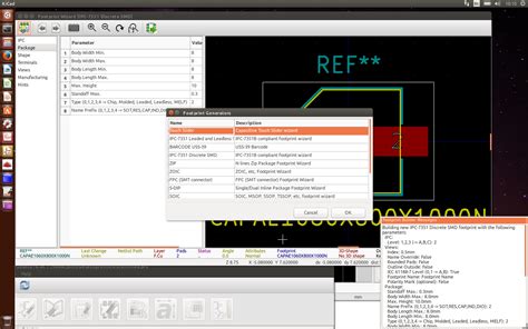
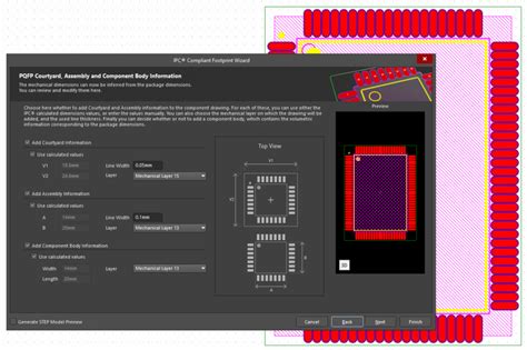
Using a PCB design tool (e.g., Altium Designer, KiCad), create the QFP footprint model according to the calculated dimensions and the guidelines provided in IPC-7351.
-
Validate the Footprint Model:
- Verify that the created QFP footprint model adheres to the IPC-7351 standard and meets the specific design requirements.

Common Challenges and Solutions in Implementing IPC Footprint Models
Challenge 1: Inconsistencies Between PCB Design Tools
Different PCB design tools may have varying implementations of IPC standards, leading to inconsistencies in footprint models.
Solution:
– Use PCB design tools that have built-in support for IPC standards and provide automated footprint generation features.
– Regularly update PCB design tools to ensure compatibility with the latest IPC standards and guidelines.
Challenge 2: Outdated or Incomplete Component Data
Component manufacturers may provide outdated or incomplete data, making it difficult to create accurate and IPC compliant footprint models.
Solution:
– Use reliable component data sources, such as vendor-supplied CAD models or IPC-validated component libraries.
– Verify component data against the latest IPC standards and guidelines to ensure accuracy and compliance.
Challenge 3: Custom or Non-Standard Components
Some designs may require custom or non-standard components that do not have predefined IPC footprint models.
Solution:
– Collaborate with component manufacturers to obtain accurate dimensional data and create custom footprint models that adhere to IPC guidelines.
– Document custom footprint models thoroughly and share them with the design team to ensure consistency and reusability.
Best Practices for Maintaining IPC Compliant Footprint Libraries
To ensure the long-term success of using IPC compliant footprint models, consider the following best practices:
-
Regularly Update Footprint Libraries: Keep footprint libraries up-to-date with the latest IPC standards and component data to ensure ongoing compliance and compatibility.
-
Implement Version Control: Use version control systems to track changes in footprint models and maintain a history of revisions for traceability and collaboration.
-
Establish a Review Process: Implement a formal review process for new and updated footprint models to ensure adherence to IPC standards and design requirements.
-
Provide Training and Resources: Educate team members on IPC standards, footprint creation guidelines, and best practices to ensure consistent and compliant footprint model usage across the organization.
The Future of IPC Footprint Models
As electronic components and manufacturing processes continue to evolve, IPC standards and footprint models will need to adapt accordingly. Some trends and developments to watch for include:
-
Miniaturization: As components become smaller and more complex, IPC standards will need to provide guidance for creating footprint models that accommodate tighter tolerances and advanced packaging technologies.
-
3D Modeling: The incorporation of 3D modeling in PCB design will require IPC standards to address the creation and validation of 3D footprint models.
-
Automated Footprint Generation: Advances in PCB design tools and component data management will enable more automated and intelligent footprint generation, reducing manual effort and ensuring compliance with IPC standards.
FAQ
Q1: What is the difference between IPC-7351 and IPC-7352?
A1: IPC-7351 provides generic requirements for surface mount design and land pattern standards, while IPC-7352 offers additional requirements and extensions for specific component types and advanced packaging technologies.
Q2: Can I use non-IPC compliant footprint models in my PCB design?
A2: While it is possible to use non-IPC compliant footprint models, it is not recommended, as it may lead to inconsistencies, manufacturing issues, and reduced reliability of the final product. Adhering to IPC standards ensures compatibility and optimal performance.
Q3: How often should I update my footprint libraries to maintain IPC compliance?
A3: It is recommended to update footprint libraries regularly, ideally with each new release of the relevant IPC standards or when significant changes in component data occur. Establishing a regular review and update process helps maintain ongoing compliance.
Q4: What should I do if I encounter a component without an IPC compliant footprint model?
A4: If you encounter a component without an IPC compliant footprint model, reach out to the component manufacturer for accurate dimensional data and create a custom footprint model that adheres to IPC guidelines. Document the custom model thoroughly and share it with your design team for consistency and reusability.
Q5: How can I ensure that my team consistently uses IPC compliant footprint models?
A5: To ensure consistent usage of IPC compliant footprint models, provide regular training and resources on IPC standards and best practices, implement a formal review process for footprint models, and use version control systems to track changes and maintain a history of revisions.
Conclusion
IPC compliant footprint models play a crucial role in ensuring consistency, reliability, and compatibility in PCB design and manufacturing. By adhering to IPC standards and following best practices for footprint creation and management, designers can save time, reduce costs, and improve the overall quality of their products.
As the electronics industry continues to evolve, staying up-to-date with the latest IPC standards and adapting footprint models accordingly will be essential for success. By embracing automation, 3D modeling, and collaborative design practices, PCB designers can navigate the challenges and opportunities presented by advancing technology and changing market demands.

No responses yet