What is Transmission Line Critical Length?
Transmission line critical length refers to the maximum length a transmission line can be before the lumped-element circuit model breaks down and transmission line effects become significant. It is an important concept in electrical engineering, especially for high-frequency applications like radio frequency (RF) circuits, where the physical dimensions of the circuit become comparable to the wavelength of the signals being transmitted.
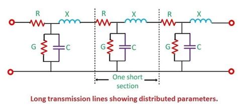
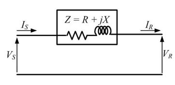
When a transmission line is shorter than its critical length, it can be treated as a simple circuit element with resistance, capacitance, and inductance. However, when the length of the transmission line exceeds the critical length, the line must be treated as a distributed parameter network, and transmission line theory must be applied to analyze its behavior.
Factors Affecting Critical Length
The critical length of a transmission line depends on several factors, including:
- Frequency of the signal: Higher frequencies have shorter wavelengths, which means the critical length is shorter for high-frequency signals.
- Dielectric constant of the insulating material: A higher dielectric constant results in a shorter critical length.
- Characteristic impedance of the line: The critical length is inversely proportional to the characteristic impedance of the line.
The critical length can be calculated using the following formula:
Lcritical = λ / 10
Where:
– Lcritical is the critical length of the transmission line
– λ is the wavelength of the signal
The wavelength can be calculated using:
λ = v / f
Where:
– v is the velocity of the signal in the transmission line
– f is the frequency of the signal
The velocity of the signal in the transmission line can be calculated using:
v = c / √εr
Where:
– c is the speed of light in a vacuum (approximately 3 × 10^8 m/s)
– εr is the relative permittivity (dielectric constant) of the insulating material
Importance of Critical Length in RF Design
Understanding and considering the critical length of transmission lines is crucial in RF circuit design. When the length of a transmission line exceeds its critical length, several phenomena can occur that affect the performance of the circuit:
- Reflections: When a signal encounters an impedance mismatch at the end of a transmission line, a portion of the signal is reflected back toward the source. These reflections can cause standing waves, which lead to voltage and current variations along the line.
- Attenuation: As the length of a transmission line increases, the signal experiences more attenuation due to conductor and dielectric losses. This attenuation can reduce the signal strength and quality at the receiving end.
- Phase shift: The phase of the signal changes as it propagates along the transmission line. This phase shift can cause issues with signal synchronization and can affect the operation of phase-sensitive circuits.
To minimize these effects, RF designers must ensure that transmission lines are kept as short as possible and that their lengths do not exceed the critical length at the operating frequency. When longer transmission lines are unavoidable, techniques such as impedance matching, using distributed parameter models, and employing quarter-wave transformers can be used to mitigate the effects of reflections and standing waves.
Example: Microstrip Transmission Lines
Microstrip transmission lines are commonly used in printed circuit board (PCB) design for RF applications. They consist of a conductive strip separated from a ground plane by a dielectric substrate. The critical length of a microstrip transmission line can be calculated using the formulas mentioned earlier.
For example, consider a microstrip line on an FR-4 substrate (εr = 4.3) operating at a frequency of 2.4 GHz. The velocity of the signal in the microstrip line can be calculated as:
v = c / √εr
  = (3 × 10^8 m/s) / √4.3
  ≈ 1.46 × 10^8 m/s
The wavelength at 2.4 GHz is:
λ = v / f
  = (1.46 × 10^8 m/s) / (2.4 × 10^9 Hz)
  ≈ 0.061 m = 6.1 cm
Therefore, the critical length of the microstrip line at 2.4 GHz is:
Lcritical = λ / 10
          = 6.1 cm / 10
          ≈ 0.61 cm = 6.1 mm
This means that for microstrip lines longer than 6.1 mm at 2.4 GHz, transmission line effects become significant, and the line must be treated as a distributed parameter network.

Analyzing Transmission Lines Above Critical Length
When a transmission line exceeds its critical length, it must be analyzed using distributed parameter models and transmission line theory. Two common methods for analyzing transmission lines are the telegraph equations and the Smith chart.
Telegraph Equations
The telegraph equations, also known as the transmission line equations, are a pair of linear differential equations that describe the voltage and current along a transmission line as functions of position and time. The equations are:
∂v(x,t) / ∂x = -R × i(x,t) - L × ∂i(x,t) / ∂t
∂i(x,t) / ∂x = -G × v(x,t) - C × ∂v(x,t) / ∂t
Where:
– v(x,t) is the voltage as a function of position (x) and time (t)
– i(x,t) is the current as a function of position (x) and time (t)
– R is the series resistance per unit length
– L is the series inductance per unit length
– G is the shunt conductance per unit length
– C is the shunt capacitance per unit length
These equations can be solved to determine the voltage and current distribution along the transmission line, as well as the input impedance and reflection coefficient at any point on the line.
Smith Chart
The Smith chart is a graphical tool used to visualize and solve problems related to transmission lines and impedance matching. It is a polar plot of the complex reflection coefficient, which represents the ratio of the reflected voltage wave to the incident voltage wave at a given point on the transmission line.
The Smith chart can be used to:
- Determine the input impedance of a transmission line at any point along its length
- Design impedance matching networks to minimize reflections and maximize power transfer
- Calculate the standing wave ratio (SWR) and voltage standing wave ratio (VSWR) on a transmission line
- Visualize the effects of adding series or shunt elements to a transmission line
By using the Smith chart, RF designers can quickly analyze and optimize transmission line circuits, ensuring proper impedance matching and minimizing the effects of reflections and standing waves.

Mitigating Transmission Line Effects
When dealing with transmission lines that exceed the critical length, several techniques can be employed to mitigate the effects of reflections, standing waves, and impedance mismatches. Some common techniques include:
- Impedance matching: By designing and implementing impedance matching networks, such as quarter-wave transformers or stub matching, the input impedance of the transmission line can be matched to the source or load impedance, minimizing reflections and maximizing power transfer.
- Termination: Properly terminating a transmission line with a load impedance equal to its characteristic impedance can eliminate reflections and standing waves. This is often done using resistive loads or matched antenna elements.
- Distributed parameter design: When transmission lines are significantly longer than the critical length, they should be designed and analyzed using distributed parameter models, taking into account the effects of reflections, standing waves, and impedance variations along the line.
- Frequency selection: In some cases, it may be possible to select an operating frequency that results in a shorter critical length, allowing the transmission line to be treated as a lumped-element circuit. This can simplify the design and analysis process.
By understanding the concept of critical length and applying these techniques, RF designers can create robust and efficient circuits that operate effectively even when transmission lines exceed the critical length.

FAQ
-
Q: What is the main difference between a lumped-element circuit model and a distributed parameter model for transmission lines?
A: A lumped-element circuit model treats the transmission line as a single circuit element with resistance, capacitance, and inductance, while a distributed parameter model considers the transmission line as a continuous system with per-unit-length parameters, taking into account the effects of reflections and standing waves along the line. -
Q: How does the operating frequency affect the critical length of a transmission line?
A: The critical length of a transmission line is inversely proportional to the operating frequency. As the frequency increases, the wavelength decreases, and the critical length becomes shorter. This means that transmission line effects become more significant at higher frequencies for a given line length. -
Q: What is the purpose of impedance matching in transmission line circuits?
A: Impedance matching is used to minimize reflections and maximize power transfer between the source, transmission line, and load. By designing and implementing impedance matching networks, such as quarter-wave transformers or stub matching, the input impedance of the transmission line can be matched to the source or load impedance, reducing reflections and standing waves. -
Q: What are the telegraph equations, and how are they used in transmission line analysis?
A: The telegraph equations, also known as the transmission line equations, are a pair of linear differential equations that describe the voltage and current along a transmission line as functions of position and time. They take into account the per-unit-length parameters of the line, such as resistance, inductance, conductance, and capacitance. These equations can be solved to determine the voltage and current distribution along the line, as well as the input impedance and reflection coefficient at any point on the line. -
Q: What is the Smith chart, and how is it used in transmission line analysis and design?
A: The Smith chart is a graphical tool used to visualize and solve problems related to transmission lines and impedance matching. It is a polar plot of the complex reflection coefficient, which represents the ratio of the reflected voltage wave to the incident voltage wave at a given point on the transmission line. The Smith chart can be used to determine the input impedance of a transmission line, design impedance matching networks, calculate standing wave ratios, and visualize the effects of adding series or shunt elements to a transmission line.
Conclusion
Transmission line critical length is a fundamental concept in RF circuit design, as it determines when a transmission line must be treated as a distributed parameter network rather than a simple lumped-element circuit. Understanding and considering the critical length is essential for designing efficient and reliable RF circuits, as it affects signal integrity, power transfer, and overall system performance.
By calculating the critical length based on factors such as operating frequency and dielectric constant, RF designers can ensure that their transmission lines are properly modeled and analyzed. When transmission lines exceed the critical length, techniques such as impedance matching, termination, and distributed parameter design can be employed to mitigate the effects of reflections, standing waves, and impedance mismatches.
As the demand for high-frequency applications continues to grow, with the proliferation of wireless communication systems, satellite links, and high-speed digital circuits, the importance of understanding and managing transmission line critical length will only increase. By mastering this concept and its associated tools, such as the telegraph equations and Smith chart, RF engineers can design and optimize circuits that push the boundaries of performance and reliability in the ever-evolving world of wireless technology.

No responses yet