
Introduction to Decoupling Capacitors
Decoupling capacitors, also known as bypass capacitors, are an essential component in digital circuit design. Their primary purpose is to provide a stable, low-impedance power supply to integrated circuits (ICs) by filtering out noise and transient voltage spikes on the power rails. Properly selecting the size and placement of decoupling capacitors is crucial for ensuring reliable operation of digital systems.
In this article, we will dive into the factors that influence the choice of decoupling capacitor size and provide guidelines for selecting appropriate values for your digital ICs.
Understanding the Role of Decoupling Capacitors
Digital ICs, such as microprocessors, microcontrollers, and logic devices, require a clean and stable power supply to function correctly. However, the switching activity of these ICs can introduce noise and voltage fluctuations on the power rails. This noise can cause several issues, including:
- Signal integrity problems
- Reduced noise margin
- Increased electromagnetic interference (EMI)
- Erratic behavior or malfunctioning of the ICs
Decoupling capacitors help mitigate these issues by serving as local energy reservoirs. They store charge and provide instantaneous current to the IC when needed, effectively decoupling the IC from the power supply. This decoupling action helps maintain a stable voltage level at the IC’s power pins, reducing noise and ensuring proper operation.
Factors Affecting Decoupling Capacitor Selection
When choosing decoupling capacitors for your digital ICs, several factors come into play. Let’s explore each of these factors in detail.
1. Frequency Response
One of the primary considerations in selecting decoupling capacitors is their frequency response. Digital ICs operate at various frequencies, ranging from a few MHz to several GHz. The decoupling capacitors must be effective at filtering out noise across the relevant frequency range.
Capacitors have a parameter called equivalent series resistance (ESR), which determines their frequency response. A lower ESR results in better high-frequency performance. Ceramic capacitors, particularly X7R and NP0 types, are commonly used for decoupling due to their low ESR and good high-frequency characteristics.
2. Capacitance Value
The capacitance value of the decoupling capacitor determines its ability to store charge and provide current to the IC. The required capacitance depends on several factors, including:
- The IC’s current consumption
- The acceptable voltage ripple
- The power supply voltage
- The frequency of operation
As a general guideline, the capacitance value should be chosen such that it provides sufficient charge storage to meet the IC’s transient current demands while keeping the voltage ripple within acceptable limits.
3. Voltage Rating
Decoupling capacitors must have a voltage rating higher than the maximum expected voltage on the power rail. This ensures that the capacitor can withstand the applied voltage without damage or degradation.
It is recommended to choose capacitors with a voltage rating at least 50% higher than the nominal power supply voltage. For example, if your digital IC operates at 3.3V, use decoupling capacitors rated for at least 6.3V.
4. Package Size and Placement
The package size and placement of decoupling capacitors are critical factors in their effectiveness. Ideally, the capacitors should be placed as close as possible to the IC’s power pins to minimize the inductance of the connection.
Surface-mount devices (SMDs) are preferred for decoupling purposes due to their small size and low inductance. Common package sizes include 0402, 0603, and 0805. The choice of package size depends on the available board space and the required capacitance value.
5. Quantity and Combination
Using a single decoupling capacitor may not provide optimal performance across the entire frequency range. It is common practice to use a combination of capacitors with different values to achieve effective decoupling.
A typical decoupling scheme includes:
- Bulk capacitors (10 μF to 100 μF): These larger capacitors provide bulk energy storage and low-frequency decoupling. They are placed near the power entry point of the board.
- Ceramic capacitors (0.01 μF to 1 μF): These smaller capacitors offer high-frequency decoupling and are placed close to the IC’s power pins.
The specific values and quantities depend on the IC’s requirements and the design constraints.

Decoupling Capacitor Selection Guidelines
Now that we understand the factors influencing decoupling capacitor selection, let’s summarize the guidelines for choosing the appropriate size:
- Determine the frequency range of interest based on the IC’s operating frequency and the expected noise spectrum.
- Select capacitors with low ESR and suitable frequency response, such as X7R or NP0 ceramic capacitors.
- Calculate the required capacitance based on the IC’s current consumption, acceptable voltage ripple, and power supply voltage.
- Choose a voltage rating at least 50% higher than the nominal power supply voltage.
- Use SMD packages and place the capacitors as close as possible to the IC’s power pins.
- Employ a combination of bulk and ceramic capacitors to achieve effective decoupling across the frequency range.
Decoupling Capacitor Size Table
To help you select the appropriate decoupling capacitor size, here’s a table with common values and their typical applications:
| Capacitor Value | Package Size | Voltage Rating | Typical Application |
|---|---|---|---|
| 0.01 μF | 0402 | 16V | High-frequency decoupling, near IC pins |
| 0.1 μF | 0603 | 25V | General-purpose decoupling |
| 1 μF | 0805 | 50V | Bulk decoupling, power entry point |
| 10 μF | 1206 | 50V | Bulk decoupling, power distribution network |
| 100 μF | Electrolytic | 50V | Bulk decoupling, power supply filtering |
Note: The values in the table are typical examples and may vary based on specific design requirements.
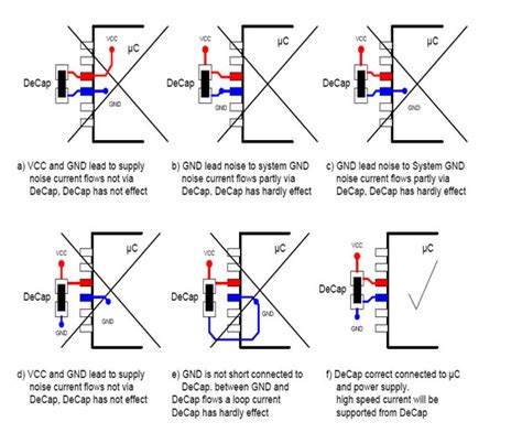
Decoupling Capacitor Placement
Proper placement of decoupling capacitors is crucial for their effectiveness. Here are some guidelines for optimal placement:
- Place decoupling capacitors as close as possible to the IC’s power pins to minimize the inductance of the connection.
- Use a separate decoupling capacitor for each power pin on the IC.
- Avoid placing decoupling capacitors too far from the IC, as this can reduce their effectiveness.
- Provide a low-impedance return path for the decoupling capacitors by using a solid ground plane.
- Minimize the trace length between the capacitor and the IC’s power pin to reduce inductance.
By following these placement guidelines, you can ensure that the decoupling capacitors provide optimal performance in your digital circuit.
Decoupling Capacitor Calculation Example
Let’s walk through an example of calculating the required decoupling capacitor size for a digital IC.
Suppose we have a microcontroller operating at 100 MHz with a current consumption of 200 mA. The power supply voltage is 3.3V, and we want to limit the voltage ripple to 50 mV.
Step 1: Determine the frequency range of interest.
The operating frequency is 100 MHz, so we need decoupling capacitors effective up to at least 100 MHz.
Step 2: Select the capacitor type and package size.
We’ll use X7R ceramic capacitors in 0402 and 0603 packages for high-frequency decoupling.
Step 3: Calculate the required capacitance.
The required capacitance can be estimated using the formula:
C = I × Δt / ΔV
where:
– C is the capacitance in farads (F)
– I is the current consumption in amperes (A)
– Δt is the time period corresponding to the highest frequency of interest (1/100 MHz = 10 ns)
– ΔV is the acceptable voltage ripple in volts (V)
Plugging in the values:
C = 200 mA × 10 ns / 50 mV
C = 2 × 10^-7 × 10^-8 / 5 × 10^-2
C = 40 nF
Step 4: Choose the capacitor values and quantities.
We’ll use a combination of capacitors:
– 2 × 0.01 μF (10 nF) in 0402 package for high-frequency decoupling
– 1 × 0.1 μF (100 nF) in 0603 package for general-purpose decoupling
– 1 × 10 μF in 1206 package for bulk decoupling
Step 5: Place the capacitors close to the IC’s power pins.
Follow the placement guidelines discussed earlier to ensure optimal performance.
By following these steps, we can select appropriate decoupling capacitors for our digital IC.
Frequently Asked Questions (FAQ)
1. What happens if I don’t use decoupling capacitors in my digital circuit?
Without decoupling capacitors, your digital circuit may experience several issues, such as:
– Increased power supply noise and voltage fluctuations
– Signal integrity problems and reduced noise margin
– Electromagnetic interference (EMI) and erratic behavior of the ICs
2. Can I use a single decoupling capacitor for all my digital ICs?
While using a single decoupling capacitor may work in some cases, it is generally recommended to use a separate decoupling capacitor for each power pin on the IC. This ensures optimal decoupling performance and minimizes the influence of one IC’s noise on another.
3. How do I choose the right voltage rating for my decoupling capacitors?
Choose decoupling capacitors with a voltage rating at least 50% higher than the nominal power supply voltage. For example, if your digital IC operates at 3.3V, use decoupling capacitors rated for at least 6.3V to provide a safety margin.
4. Can I use electrolytic capacitors for decoupling?
Electrolytic capacitors are generally not suitable for high-frequency decoupling due to their higher ESR and lower frequency response compared to ceramic capacitors. However, they can be used for bulk decoupling and power supply filtering at lower frequencies.
5. What is the purpose of using different capacitor values in a decoupling scheme?
Using a combination of capacitor values helps achieve effective decoupling across a wide frequency range. Larger capacitors (e.g., 10 μF to 100 μF) provide bulk energy storage and low-frequency decoupling, while smaller capacitors (e.g., 0.01 μF to 1 μF) offer high-frequency decoupling and are placed close to the IC’s power pins.
Conclusion
Selecting the appropriate size of decoupling capacitors is essential for ensuring the reliable operation of digital ICs. By considering factors such as frequency response, capacitance value, voltage rating, package size, and placement, you can effectively decouple your digital circuits and minimize power supply noise.
Remember to use a combination of bulk and ceramic capacitors, place them close to the IC’s power pins, and provide a low-impedance return path through a solid ground plane. By following the guidelines and examples provided in this article, you can confidently choose the right decoupling capacitors for your digital design.
No responses yet