Introduction to PCB Outline and Mechanical Files
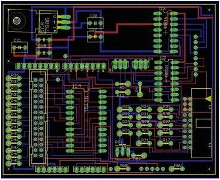
When designing a printed circuit board (PCB), one of the crucial aspects is defining the PCB outline. The PCB outline determines the physical shape and size of the board, which is essential for ensuring proper fit and functionality within the intended enclosure or system. To accurately create the PCB outline, designers often rely on importing mechanical files that contain the necessary geometric information.
Importance of Choosing the Right File Format
Choosing the appropriate file format for importing mechanical files is crucial for several reasons:
-
Compatibility: The file format must be compatible with the PCB design software being used. Different PCB design tools support various file formats, and selecting a format that is not supported can lead to import failures or inaccuracies.
-
Precision: The file format should preserve the precise geometric information of the mechanical design. Any loss of precision during the import process can result in discrepancies between the intended outline and the actual PCB shape.
-
Ease of Use: The chosen file format should be easy to work with, allowing for smooth import and manipulation within the PCB design software. Complex or proprietary file formats may require additional steps or specialized tools, adding unnecessary complexity to the design process.
Popular File Formats for PCB Outline Import
There are several file formats commonly used for importing mechanical files as PCB outlines. Each format has its own characteristics, advantages, and limitations. Let’s explore some of the popular file formats:
1. DXF (Drawing Exchange Format)
DXF is a widely supported file format for exchanging 2D and 3D design data. It is an ASCII-based format that was developed by Autodesk and is compatible with many CAD (Computer-Aided Design) and PCB design software packages. DXF files can contain various geometric entities, such as lines, arcs, circles, and polygons, making them suitable for representing PCB outlines.
Advantages of DXF:
– Widely supported by PCB design tools and CAD software
– Preserves the accuracy of geometric information
– ASCII-based format, making it human-readable and easier to debug if needed
Limitations of DXF:
– Limited to 2D geometry, so it may not be suitable for complex 3D mechanical designs
– File size can be larger compared to binary formats
2. STEP (Standard for the Exchange of Product Model Data)
STEP, also known as ISO 10303, is a standardized file format for exchanging 3D CAD data. It is a neutral format that can be used to transfer product information between different software systems. STEP files can contain both geometric and non-geometric data, including materials, tolerances, and product structure.
Advantages of STEP:
– Supports both 2D and 3D geometry
– Widely adopted standard in the engineering and manufacturing industries
– Rich in product information beyond just geometry
Limitations of STEP:
– Complexity of the format may require specialized tools for viewing and manipulation
– Not all PCB design software may have native support for STEP import
3. DWG (Drawing)
DWG is a proprietary binary file format developed by Autodesk for storing 2D and 3D design data. It is the native format used by AutoCAD, a popular CAD software. DWG files can contain various geometric entities and are widely used in the engineering and construction industries.
Advantages of DWG:
– High compatibility with Autodesk software, including AutoCAD and Autodesk Inventor
– Supports both 2D and 3D geometry
– Efficient binary format resulting in smaller file sizes
Limitations of DWG:
– Proprietary format owned by Autodesk, which may limit interoperability with other software
– Requires compatible software or viewers to access and manipulate the files
4. IGES (Initial Graphics Exchange Specification)
IGES is a neutral file format for exchanging 2D and 3D CAD data between different software systems. It was developed by the U.S. National Bureau of Standards (now known as the National Institute of Standards and Technology) and has been widely used in the engineering industry.
Advantages of IGES:
– Supports both 2D and 3D geometry
– Neutral format allowing for data exchange between different CAD systems
– Widely supported by various CAD and PCB design software
Limitations of IGES:
– Limited support for some advanced geometric entities and features
– May not preserve all product information, such as materials and tolerances

Comparison Table of File Formats
| File Format | Compatibility | Precision | Ease of Use | 2D/3D Support |
|---|---|---|---|---|
| DXF | High | High | Easy | 2D |
| STEP | Medium | High | Medium | 2D and 3D |
| DWG | Medium | High | Easy | 2D and 3D |
| IGES | High | Medium | Medium | 2D and 3D |

Choosing the Right File Format for PCB Outline Import
When selecting the file format for importing mechanical files as PCB outlines, consider the following factors:
-
Compatibility with your PCB design software: Ensure that the chosen file format is supported by your specific PCB design tool. Consult the software documentation or seek guidance from the software vendor if needed.
-
Precision requirements: Evaluate the level of precision required for your PCB outline. If high accuracy is crucial, choose a file format that preserves the geometric information without any loss or approximation.
-
Collaboration with mechanical engineers: Consider the file formats commonly used by mechanical engineers or the CAD software they work with. Choosing a file format that is compatible with their tools can streamline the collaboration process and avoid any data exchange issues.
-
Simplicity and ease of use: Opt for a file format that is straightforward to work with and does not require extensive preprocessing or conversion steps. This can save time and reduce the chances of errors during the import process.

Best Practices for PCB Outline Import
To ensure a smooth and accurate import of mechanical files as PCB outlines, follow these best practices:
-
Communicate with the mechanical engineering team: Collaborate closely with the mechanical engineers to understand their design intent, constraints, and any specific requirements for the PCB outline. Clear communication can help avoid misinterpretations and ensure that the imported outline aligns with the mechanical design.
-
Use a clean and simplified mechanical file: Request a mechanical file that contains only the necessary geometric information for the PCB outline. Remove any extraneous details, annotations, or layers that are not relevant to the PCB design. A clean and simplified file can reduce the chances of import errors and improve the efficiency of the import process.
-
Verify the imported outline: After importing the mechanical file, carefully review the resulting PCB outline. Check for any discrepancies, missing features, or unintended modifications. Compare the imported outline with the original mechanical design to ensure accuracy and completeness.
-
Perform design rule checks: Run design rule checks (DRC) on the imported PCB outline to identify any violations or issues related to manufacturing constraints. Resolve any detected problems to ensure that the PCB outline is compliant with the fabrication requirements.
-
Maintain version control: Implement a robust version control system to track changes and revisions to both the mechanical files and the PCB design files. This helps maintain synchronization between the mechanical and electrical domains, especially when iterative changes are made to the design.
Frequently Asked Questions (FAQ)
-
What is the most widely supported file format for importing PCB outlines?
DXF (Drawing Exchange Format) is one of the most widely supported file formats for importing PCB outlines. It is compatible with many PCB design tools and CAD software packages, making it a popular choice for data exchange. -
Can I import 3D mechanical files as PCB outlines?
Yes, you can import 3D mechanical files as PCB outlines, but you may need to use file formats that support 3D geometry, such as STEP or DWG. However, keep in mind that PCB design primarily deals with 2D geometry, so the 3D information may be flattened or projected onto a 2D plane during the import process. -
What should I do if my PCB design software doesn’t support the file format provided by the mechanical team?
If your PCB design software doesn’t support the file format provided by the mechanical team, you have a few options: - Request the mechanical team to provide the file in a compatible format.
- Use a third-party file converter to convert the mechanical file into a format supported by your PCB design software.
-
Explore if your PCB design software has any built-in import options or plugins that can handle the specific file format.
-
How can I ensure the accuracy of the imported PCB outline?
To ensure the accuracy of the imported PCB outline, follow these steps: - Use a file format that preserves the geometric information without loss of precision.
- Verify the imported outline by comparing it with the original mechanical design.
- Perform design rule checks to identify any violations or issues related to manufacturing constraints.
-
Collaborate closely with the mechanical engineering team to validate the imported outline.
-
What should I do if there are discrepancies between the imported PCB outline and the mechanical design?
If you encounter discrepancies between the imported PCB outline and the mechanical design, take the following actions: - Double-check the import process to ensure that no errors occurred during the file conversion or import.
- Communicate with the mechanical engineering team to clarify any ambiguities or inconsistencies.
- Review the mechanical file for any missing or incorrect information that may have caused the discrepancies.
- Iterate and refine the import process until the PCB outline accurately represents the mechanical design intent.
Conclusion
Selecting the appropriate file format for importing mechanical files as PCB outlines is crucial for ensuring accurate and efficient PCB design. DXF, STEP, DWG, and IGES are among the popular file formats used for this purpose, each with its own advantages and limitations. When choosing a file format, consider factors such as compatibility with your PCB design software, precision requirements, collaboration with mechanical engineers, and ease of use.
By following best practices, such as communicating effectively with the mechanical team, using clean and simplified mechanical files, verifying the imported outline, performing design rule checks, and maintaining version control, you can streamline the PCB outline import process and minimize the chances of errors.
Remember, the key to successful PCB outline import is close collaboration between the electrical and mechanical domains, ensuring that the PCB design accurately reflects the mechanical design intent. By selecting the right file format and following best practices, you can create precise and reliable PCB outlines that form the foundation of a successful PCB design.

No responses yet