What is a PCB Current Calculator?
A PCB Current Calculator is a tool used to determine the current carrying capacity of a printed circuit board (PCB) trace. It takes into account various factors such as the trace width, thickness, temperature rise, and ambient temperature to calculate the maximum current that can safely flow through a PCB trace without causing damage or excessive heating.
PCB designers use current calculators to ensure that the traces on their boards are appropriately sized to handle the expected current flow. This is critical for the proper functioning and reliability of electronic devices.
Why is Calculating PCB Current Important?
Calculating the current carrying capacity of PCB traces is essential for several reasons:
-
Avoiding Overheating: If a trace is too narrow for the amount of current flowing through it, it can overheat and cause damage to the PCB or surrounding components. This can lead to device failure or even pose a fire hazard.
-
Maintaining Signal Integrity: Improper trace sizing can lead to voltage drops and signal degradation, which can affect the performance of the electronic device.
-
Ensuring Reliability: Properly sized traces help ensure the long-term reliability of the PCB and the device it is used in. Overheating and signal integrity issues can cause premature failure of components and devices.
-
Meeting Safety Standards: Many industries have safety standards and regulations that specify the minimum trace sizes for a given current. Adhering to these standards is crucial for ensuring the safety and reliability of electronic devices.
Factors That Affect PCB trace current Capacity
Several factors influence the current carrying capacity of a PCB trace. These include:
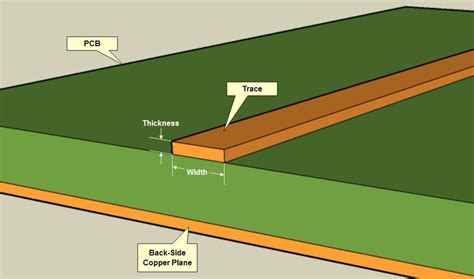
Trace Width
The width of a trace is one of the most significant factors in determining its current carrying capacity. Wider traces can handle more current than narrower traces. This is because a wider trace has a larger cross-sectional area, which allows for more electrons to flow through it.
Trace Thickness
The thickness of a trace, also known as its height, also plays a role in its current carrying capacity. Thicker traces can handle more current than thinner traces. This is because a thicker trace has a larger cross-sectional area, just like a wider trace.
Temperature Rise
The amount of current a trace can handle is also dependent on the acceptable temperature rise. As current flows through a trace, it generates heat. The more current that flows, the more heat is generated. The acceptable temperature rise is the amount of heating that a trace can safely handle without causing damage to the PCB or surrounding components.
Ambient Temperature
The ambient temperature, or the temperature of the environment around the PCB, also affects a trace’s current carrying capacity. In a higher ambient temperature, a trace can handle less current because it is already being subjected to additional heat from its surroundings.
Trace Length
The length of a trace can also affect its current carrying capacity, particularly if the trace is very long. Longer traces have more resistance, which can lead to a greater voltage drop and more heating.
Copper Weight
PCBs are typically made with copper traces, and the weight of the copper used can affect a trace’s current carrying capacity. Heavier copper weights, such as 2 oz. or 3 oz. copper, can handle more current than lighter copper weights, like 1/2 oz. or 1 oz. copper.

How to Use a PCB Current Calculator
Using a PCB current calculator is relatively straightforward. Here are the general steps:
-
Gather necessary information: You’ll need to know the width and thickness of your trace, the acceptable temperature rise, the ambient temperature, and the length of the trace.
-
Input data: Enter this information into the PCB current calculator. Many calculators will have fields for each of these variables.
-
Choose your units: Make sure to select the correct units for each variable. Trace width and thickness are typically in mils (thousandths of an inch) or millimeters, temperature is in Celsius, and length is in inches or millimeters.
-
Calculate: Once you’ve entered all the necessary data, the calculator will give you the maximum current capacity for your trace.
Here’s an example of how to use a PCB current calculator:
Let’s say you have a trace that is 10 mils wide, 1 oz. copper weight (1.4 mils thick), 10 inches long, and you’re allowing for a 10°C temperature rise in a 25°C ambient environment.
| Variable | Value |
|---|---|
| Trace Width | 10 mils |
| Copper Weight | 1 oz. (1.4 mils thick) |
| Trace Length | 10 inches |
| Temperature Rise | 10°C |
| Ambient Temperature | 25°C |
Inputting these values into a PCB current calculator, you might get a result of around 1.2 amps. This means that this trace can safely handle up to 1.2 amps of current under these conditions.
PCB Current Calculator Formula
Many PCB current calculators use a formula based on IPC-2221, a generic standard for the design of printed boards. The formula takes into account the cross-sectional area of the trace, the temperature rise, and the resistivity of the copper. Here’s the formula:
I = (ΔT / (ρ * L / A)) ^ 0.44
Where:
- I = Current in amps
- ΔT = Temperature rise in °C
- ρ (rho) = Resistivity of copper (1.68 * 10^-8 Ω·m at 20°C)
- L = Length of trace in meters
- A = Cross-sectional area of trace in square meters
The cross-sectional area (A) is calculated by multiplying the trace width by the trace thickness.
For example, let’s calculate the current capacity for a trace that is 20 mils wide, 2 oz. copper weight (2.8 mils thick), 5 inches long, with a 15°C temperature rise.
First, convert the dimensions to meters:
- 20 mils = 0.0005 m
- 2.8 mils = 0.00007 m
- 5 inches = 0.127 m
Calculate the cross-sectional area:
A = 0.0005 m * 0.00007 m = 3.5 * 10^-8 m^2
Now, plug these values into the formula:
I = (15 / (1.68 * 10^-8 * 0.127 / 3.5 * 10^-8)) ^ 0.44
= (15 / (1.68 * 10^-8 * 3.629)) ^ 0.44
= (15 / 6.096 * 10^-8) ^ 0.44
= (246,189,917) ^ 0.44
= 2.21 amps
So, according to this calculation, this trace can handle about 2.21 amps of current.
Online PCB Current Calculators
There are many online PCB current calculators available that can make these calculations easier. Here are a few popular options:
- 4PCB.com Current Carrying Capacity Calculator
- EEWeb.com PCB Trace Width Calculator
- Digi-Key Electronics PCB Trace Width Calculator
These calculators typically have fields for you to input your trace parameters and will calculate the maximum current capacity based on those inputs.
PCB Current Calculator Apps
In addition to online calculators, there are also mobile apps available for calculating PCB trace currents. These can be handy for designers who need to make quick calculations on the go. Here are a couple of examples:
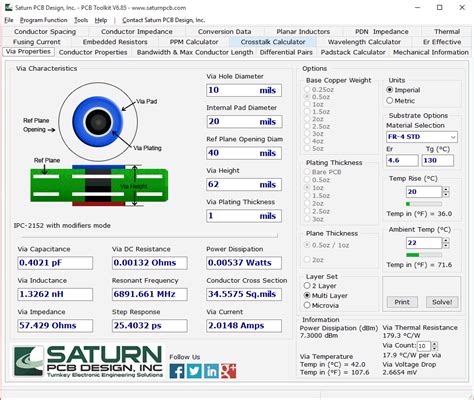
- PCB Toolkit (iOS, Android)
- EE Toolkit (iOS, Android)
These apps often include other useful electronics-related calculators and tools as well.
IPC-2221 Standards for PCB Trace Current
IPC-2221 is a generic standard for the design of printed boards that includes guidelines for determining the current carrying capacity of PCB traces. Many PCB current calculators and formulas are based on this standard.
IPC-2221 provides charts that specify the maximum current for traces of different widths, thicknesses, and temperature rises. Here’s a simplified version of one of these charts:
| Trace Width (mils) | 1 oz. Copper (amps) | 2 oz. Copper (amps) |
|---|---|---|
| 10 | 1.0 | 1.4 |
| 20 | 2.0 | 2.8 |
| 30 | 3.0 | 4.2 |
| 40 | 4.0 | 5.6 |
| 50 | 5.0 | 7.0 |
These values assume a temperature rise of 10°C above ambient. For other temperature rises, the values would be different.
Designers can use these charts as a quick reference, but for more precise calculations, it’s best to use a PCB current calculator or the IPC-2221 formula.
Frequently Asked Questions (FAQ)
-
What happens if I use a trace that is too narrow for the current it needs to carry?
If a trace is too narrow for the current it’s carrying, it can overheat. This can lead to damage of the PCB, surrounding components, or even the entire device. In extreme cases, it can pose a fire hazard. -
Can I just use the widest trace possible to ensure it can handle the current?
While using a very wide trace might ensure it can handle the current, it’s not always the best solution. Wider traces take up more space on the PCB, which can make routing more difficult and limit the space available for other components. It’s best to use a PCB current calculator to determine the appropriate trace width for your specific needs. -
What if I’m not sure about the ambient temperature or acceptable temperature rise for my PCB?
If you’re unsure about the ambient temperature, it’s best to assume a higher temperature to be on the safe side. For example, if your device will be used in a variety of environments, you might assume a 40°C ambient temperature. As for temperature rise, 10°C is a common default value, but you may need to adjust this based on your specific application and the temperature sensitivity of your components. -
Can I use a PCB current calculator for traces on the inner layers of my PCB?
Yes, PCB current calculators can be used for traces on any layer of your PCB. However, keep in mind that inner layers may have different ambient temperatures due to their position within the board. -
What if my trace needs to handle more current than a single trace can support?
If your trace needs to handle more current than a single trace can support, you have a few options. You can use a wider trace, use a thicker copper weight, or use multiple traces in parallel. When using multiple traces in parallel, be sure to use thermal reliefs to connect the traces to pads to prevent solder from wicking up the traces during soldering.
Conclusion
The PCB current calculator is an essential tool for any PCB designer. It allows you to determine the appropriate trace width for your design, ensuring that your traces can safely handle the required current without overheating or causing damage.
By understanding the factors that affect a trace’s current carrying capacity and how to use a PCB current calculator, you can design more reliable and robust PCBs. Always remember to consider the ambient temperature, acceptable temperature rise, trace thickness, and length in your calculations.
When in doubt, it’s always better to err on the side of caution and use a slightly wider trace than necessary. This can help ensure the long-term reliability and safety of your PCB and the device it powers.
No responses yet