Introduction to Pulse-Width Modulation (PWM)
Pulse-Width Modulation (PWM) is a powerful technique used in various applications, from controlling the brightness of LEDs to regulating the speed of motors. It has become an essential tool for engineers, hobbyists, and anyone working with electronic systems. In this ultimate guide, we will dive deep into the basics of PWM, exploring its principles, applications, and practical implementations.
What is Pulse-Width Modulation?
Pulse-Width Modulation is a method of encoding analog signal levels into a digital pulse signal. It involves modulating the width of the pulses in a square wave signal to control the average power delivered to a load. By varying the duty cycle of the pulses, PWM allows for precise control over the amount of power supplied to a device.
Key Concepts of PWM
- Duty Cycle: The ratio of the pulse width (on-time) to the total period of the signal.
- Frequency: The number of pulses per second, measured in Hertz (Hz).
- Resolution: The number of discrete duty cycle steps available within a PWM period.
How PWM Works
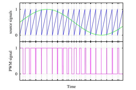
PWM operates by rapidly switching a power source on and off, creating a series of pulses. The width of these pulses determines the average voltage delivered to the load. By adjusting the pulse width, you can effectively control the power output.
PWM Signal Generation
PWM signals are typically generated using a microcontroller or a dedicated PWM controller. These devices have built-in timers and comparators that allow for precise control over the pulse width and frequency.
PWM Signal Characteristics
- High Level: The maximum voltage of the PWM signal, usually the supply voltage (Vcc).
- Low Level: The minimum voltage of the PWM signal, typically ground (GND).
- Period: The time taken for one complete cycle of the PWM signal.
Duty Cycle and Average Voltage
The duty cycle is a crucial parameter in PWM. It represents the percentage of time the signal is in the high state (on) during one period. By varying the duty cycle, you can control the average voltage delivered to the load.
Duty Cycle Calculation:
Duty Cycle = (Pulse Width / Period) × 100%
Average Voltage Calculation:
Average Voltage = (Duty Cycle / 100%) × Vcc
| Duty Cycle | Average Voltage (Vcc = 5V) |
|---|---|
| 0% | 0V |
| 25% | 1.25V |
| 50% | 2.5V |
| 75% | 3.75V |
| 100% | 5V |

Applications of PWM
PWM finds applications in a wide range of fields, from automotive systems to home automation. Let’s explore some common use cases.
LED Brightness Control
One of the most popular applications of PWM is controlling the brightness of LEDs. By varying the duty cycle of the PWM signal, you can adjust the perceived brightness of an LED.
LED Brightness Control Steps
- Connect the LED to a PWM-capable pin on the microcontroller.
- Set the PWM frequency appropriate for the LED (typically a few kilohertz).
- Adjust the duty cycle to control the brightness (0% for off, 100% for maximum brightness).
Motor Speed Control
PWM is extensively used in motor control applications, particularly for DC motors. By controlling the duty cycle of the PWM signal, you can regulate the speed of the motor.
Motor Speed Control Steps
- Connect the motor to a suitable motor driver or H-bridge circuit.
- Set the PWM frequency appropriate for the motor (usually a few kilohertz).
- Adjust the duty cycle to control the motor speed (0% for stopped, 100% for maximum speed).
Servo Motor Control
Servo motors are widely used in robotics and automation applications. PWM is employed to control the position of the servo motor by varying the pulse width.
Servo Motor Control Steps
- Connect the servo motor to a PWM-capable pin on the microcontroller.
- Set the PWM frequency to the standard servo frequency (typically 50Hz).
- Adjust the pulse width to control the servo position (usually 1ms for 0°, 1.5ms for 90°, and 2ms for 180°).

Advantages of PWM
PWM offers several advantages over other control techniques:
- Efficiency: PWM is highly efficient as it minimizes power losses in the switching devices.
- Precision: PWM allows for precise control over the average voltage or power delivered to a load.
- Simplicity: PWM can be easily implemented using microcontrollers or dedicated PWM controllers.
- Flexibility: PWM can be used to control a wide range of devices, from LEDs to motors.

Implementing PWM
Implementing PWM involves configuring the microcontroller or PWM controller to generate the desired PWM signal. Here’s a general outline of the steps involved:
- Hardware Setup:
- Connect the load (LED, motor, etc.) to the appropriate PWM-capable pin on the microcontroller.
-
Ensure proper power supply and ground connections.
-
Software Configuration:
- Initialize the PWM module on the microcontroller.
- Set the PWM frequency and resolution based on the application requirements.
-
Configure the PWM pin as an output.
-
Duty Cycle Adjustment:
- Calculate the required duty cycle based on the desired control parameter (brightness, speed, position).
-
Update the duty cycle value in the PWM module registers.
-
Continuous Control:
- Monitor any changes in the control parameter.
- Adjust the duty cycle accordingly to maintain the desired output.
Here’s an example code snippet in Arduino for controlling an LED’s brightness using PWM:
const int ledPin = 9;  // PWM pin connected to the LED

void setup() {
  pinMode(ledPin, OUTPUT);  // Set the LED pin as an output
}

void loop() {
  // Increase brightness gradually
  for (int dutyCycle = 0; dutyCycle <= 255; dutyCycle++) {
    analogWrite(ledPin, dutyCycle);
    delay(10);
  }

  // Decrease brightness gradually
  for (int dutyCycle = 255; dutyCycle >= 0; dutyCycle--) {
    analogWrite(ledPin, dutyCycle);
    delay(10);
  }
}
Practical Considerations
When working with PWM, there are a few practical considerations to keep in mind:
-
Frequency Selection: Choose an appropriate PWM frequency based on the application. Higher frequencies are suitable for LEDs to avoid visible flickering, while lower frequencies are often used for motor control.
-
Resolution: Consider the resolution of the PWM signal, which determines the number of discrete duty cycle steps available. Higher resolution allows for finer control but may require more computational resources.
-
Filtering: In some cases, you may need to filter the PWM signal to smooth out the pulses and obtain a cleaner analog signal. Low-pass filters can be used to remove the high-frequency components of the PWM signal.
-
Power Handling: Ensure that the PWM-controlled devices can handle the maximum current and voltage ratings. Use appropriate driver circuits or power stages when controlling high-power loads.
Conclusion
Pulse-Width Modulation (PWM) is a versatile and powerful technique for controlling various electronic devices. By modulating the width of pulses in a digital signal, PWM allows for precise control over the average power delivered to a load. Whether you’re working on LED lighting, motor control, or servo positioning, understanding PWM is essential for effective implementation.
In this ultimate guide, we covered the basics of PWM, including its principles, applications, and practical considerations. By mastering PWM, you can unlock a wide range of possibilities in your electronic projects and create efficient and precise control systems.
Frequently Asked Questions (FAQ)
-
What is the difference between PWM and analog control?
PWM is a digital control technique that uses pulses of varying widths to control the average power delivered to a load. Analog control, on the other hand, uses a continuous voltage or current signal to control the device directly. PWM offers advantages such as efficiency, precision, and easier implementation with digital systems. -
Can PWM be used for AC devices?
PWM is primarily used for controlling DC devices. However, it can be used in conjunction with inverter circuits to control AC devices indirectly. The PWM signal is used to control the inverter, which in turn generates the AC waveform for the device. -
What is the relationship between PWM frequency and resolution?
The PWM frequency and resolution are inversely related. Higher frequencies result in lower resolution, as there are fewer duty cycle steps available within each PWM period. Conversely, lower frequencies allow for higher resolution, providing more granular control over the duty cycle. -
How do I choose the appropriate PWM frequency for my application?
The choice of PWM frequency depends on the specific application. For LED brightness control, frequencies in the kilohertz range are commonly used to avoid visible flickering. Motor control applications typically use frequencies in the range of a few kilohertz. Servo motors require a specific frequency, usually around 50Hz. It’s important to consult the device specifications and consider the response time and filtering requirements when selecting the PWM frequency. -
Can I use PWM to control multiple devices simultaneously?
Yes, PWM can be used to control multiple devices simultaneously. Most microcontrollers and PWM controllers have multiple PWM channels, allowing independent control of multiple devices. However, it’s important to consider the power requirements and ensure that the controller can handle the combined load of all the devices.
No responses yet