Introduction to NB2DSK01
The NB2DSK01 is a development board that combines a powerful microcontroller with a robust SPI interface. It is designed to simplify the process of developing and testing SPI-based applications, offering a user-friendly environment for both experienced engineers and beginners alike. The board is equipped with a range of features that make it suitable for a variety of use cases, including:
- High-speed SPI communication
- Multiple SPI channels
- Flexible clock configuration
- Interrupt-driven operation
- Low power consumption
Key Features of NB2DSK01
| Feature | Description |
|---|---|
| Microcontroller | High-performance, low-power MCU with ample memory and peripherals |
| SPI Interface | Multiple SPI channels with configurable clock speed and mode |
| GPIO Pins | Expandable input/output pins for connecting sensors, actuators, and other devices |
| Power Management | Efficient power management system for low power consumption |
| Programming Interface | USB and JTAG interfaces for easy programming and debugging |
SPI Communication Overview
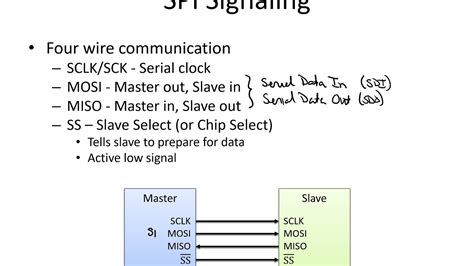
SPI is a synchronous, full-duplex, serial communication protocol widely used in embedded systems and IoT devices. It provides a simple and efficient way to transfer data between a master device (usually a microcontroller) and one or more slave devices (such as sensors, displays, or memory chips). SPI communication involves four main signals:
- SCLK (Serial Clock): Generated by the master device to synchronize data transfer
- MOSI (Master Out, Slave In): Data line for sending data from the master to the slave
- MISO (Master In, Slave Out): Data line for sending data from the slave to the master
- SS (Slave Select): Signal used by the master to select the desired slave device
Advantages of SPI Communication
SPI offers several advantages over other serial communication protocols:
- High-speed data transfer (up to several MHz)
- Full-duplex operation (simultaneous data transmission and reception)
- Simple hardware implementation
- Low power consumption
- Widely supported by microcontrollers and peripheral devices

NB2DSK01 SPI System Architecture
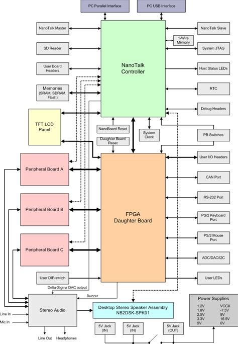
The NB2DSK01 SPI system is built around a powerful microcontroller that acts as the master device. The microcontroller is connected to multiple SPI channels, each of which can be configured independently to communicate with different slave devices. The board also features a range of GPIO pins that can be used for various purposes, such as controlling external devices or receiving input from sensors.
Microcontroller Specifications
The NB2DSK01 is equipped with a high-performance microcontroller that offers the following specifications:
| Specification | Description |
|---|---|
| Core | 32-bit ARM Cortex-M4 with FPU |
| Clock Speed | Up to 180 MHz |
| Flash Memory | 512 KB |
| SRAM | 128 KB |
| SPI Channels | 4 (configurable) |
| GPIO Pins | 32 (expandable) |
| Power Consumption | Low power modes available |
SPI Channel Configuration
Each SPI channel on the NB2DSK01 can be configured independently to suit the requirements of the connected slave device. The following parameters can be adjusted:
- Clock speed (up to 30 MHz)
- Clock polarity (CPOL)
- Clock phase (CPHA)
- Data size (8, 16, or 32 bits)
- Slave select mode (hardware or software)
By configuring the SPI channels appropriately, the NB2DSK01 can communicate effectively with a wide range of slave devices, such as sensors, displays, memory chips, and more.

Using the NB2DSK01 SPI System
To utilize the NB2DSK01 SPI system effectively, developers need to follow a few key steps:
- Connect the desired slave devices to the appropriate SPI channels on the board
- Configure the SPI channels according to the requirements of the slave devices
- Write the necessary firmware to control the SPI communication and process the data
- Compile and upload the firmware to the NB2DSK01 microcontroller
- Test and debug the application using the provided programming interfaces
Example: Interfacing with a Temperature Sensor
Let’s consider an example where we want to use the NB2DSK01 to interface with a temperature sensor via SPI. The steps involved would be as follows:
- Connect the temperature sensor to one of the SPI channels on the NB2DSK01
- Configure the SPI channel with the appropriate clock speed, polarity, and phase settings
- Write the firmware to initialize the SPI communication, read the temperature data from the sensor, and process it as required
- Compile and upload the firmware to the NB2DSK01 microcontroller
- Test the application by monitoring the temperature readings and verifying their accuracy
Code Snippet: Initializing SPI Communication
Here’s a sample code snippet in C that demonstrates how to initialize SPI communication on the NB2DSK01:
#include "spi.h"

void spi_init(void) {
    // Enable clock for SPI peripheral
    RCC->APB2ENR |= RCC_APB2ENR_SPI1EN;

    // Configure SPI pins
    GPIOA->MODER &= ~(GPIO_MODER_MODER5 | GPIO_MODER_MODER6 | GPIO_MODER_MODER7);
    GPIOA->MODER |= (GPIO_MODER_MODER5_1 | GPIO_MODER_MODER6_1 | GPIO_MODER_MODER7_1);
    GPIOA->AFR[0] |= (5 << GPIO_AFRL_AFSEL5_Pos) | (5 << GPIO_AFRL_AFSEL6_Pos) | (5 << GPIO_AFRL_AFSEL7_Pos);

    // Configure SPI settings
    SPI1->CR1 = SPI_CR1_MSTR | SPI_CR1_SSI | SPI_CR1_SSM | SPI_CR1_SPE | SPI_CR1_BR_0;
    SPI1->CR2 = SPI_CR2_DS_0 | SPI_CR2_DS_1 | SPI_CR2_DS_2;
}
This code initializes the SPI1 peripheral on the NB2DSK01, configures the necessary GPIO pins, and sets the appropriate SPI settings such as master mode, baud rate, and data size.

Conclusion
The NB2DSK01 SPI system is a powerful and flexible solution for developers working on SPI-based applications. With its high-performance microcontroller, multiple SPI channels, and user-friendly features, the NB2DSK01 simplifies the process of designing, testing, and deploying SPI-based projects. By understanding the key components and capabilities of this development board, engineers can create innovative and efficient applications across a wide range of industries, from automotive to healthcare to industrial automation.
Frequently Asked Questions (FAQ)
-
Q: What is the maximum clock speed supported by the NB2DSK01 SPI channels?
A: The NB2DSK01 SPI channels can support clock speeds up to 30 MHz, allowing for high-speed data transfer between the master and slave devices. -
Q: How many SPI channels are available on the NB2DSK01?
A: The NB2DSK01 features four SPI channels, each of which can be configured independently to communicate with different slave devices. -
Q: Can the NB2DSK01 be powered by a battery?
A: Yes, the NB2DSK01 can be powered by a battery thanks to its efficient power management system and low power consumption. However, the specific battery requirements may vary depending on the application and connected devices. -
Q: Is it possible to expand the number of GPIO pins on the NB2DSK01?
A: Yes, the NB2DSK01 allows for the expansion of GPIO pins through the use of additional hardware such as GPIO expanders or multiplexers. This enables developers to connect a larger number of sensors, actuators, or other devices to the board. -
Q: What programming languages can be used to develop applications for the NB2DSK01?
A: The NB2DSK01 can be programmed using a variety of languages, including C, C++, and Python. The choice of language depends on the specific requirements of the project and the preferences of the developer. The board also supports popular development environments such as Arduino IDE and Mbed OS.

No responses yet