Introduction to the NanoBoard RTC
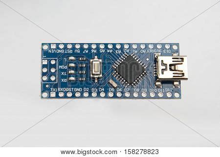
The NanoBoard 3000 is a compact development board designed for embedded systems and Internet of Things (IoT) applications. One key feature of the NanoBoard is its built-in Serial Peripheral Interface (SPI) Real Time Clock (RTC) module. An RTC provides accurate timekeeping functionality to an embedded system, allowing it to maintain the current time and date even when the main power is off.
The NanoBoard’s RTC is implemented using a dedicated chip that communicates with the board’s main microcontroller over the SPI bus. SPI is a synchronous serial communication protocol that operates in full duplex mode, enabling fast data transfer between the microcontroller and peripheral devices like the RTC.
Key Features of the NanoBoard RTC
The NanoBoard 3000’s RTC module offers several important features and capabilities:
| Feature | Description |
|---|---|
| Accurate Timekeeping | Maintains current time/date with high precision, typically +/- 2ppm |
| Battery Backup | Retains time when main power is off via coin cell battery |
| SPI Interface | Communicates with microcontroller using SPI for fast data transfer |
| Alarm Function | Can be programmed to generate an interrupt at a specific time |
| Calendar Function | Automatically handles leap years and different length months |
| Low Power Consumption | Draws very little current to maximize battery life |
Accurate Timekeeping
The primary purpose of an RTC is to provide the embedded system with an accurate source of the current date and time. The NanoBoard RTC accomplishes this with a dedicated oscillator circuit that is optimized for high stability and low drift over time and temperature variations.
Typical RTCs, including the one on the NanoBoard, maintain accuracy to within +/- 2 parts per million (ppm). This equates to a worst case error of about one minute per year, though in practice the error is often significantly less. Such accuracy is more than sufficient for most embedded applications.
Battery Backup
To maintain the time and date when the main power to the embedded system is switched off, the NanoBoard RTC includes a battery backup circuit. This consists of a holder for a 3V coin cell battery, usually a CR2032 lithium battery.
When main power is present, the RTC runs off the board’s power supply and the coin cell is not used. If main power is lost, the RTC automatically switches over to the battery to maintain timekeeping. A fresh CR2032 can power the RTC for several years in the absence of main power due to the low power design of the RTC chip.
SPI Interface
The NanoBoard RTC connects to the board’s main microcontroller through a SPI interface. SPI is a widely used synchronous serial protocol that provides full duplex communication over a shared clock line (SCK), a master-output-slave-input (MOSI) data line, a master-input-slave-output (MISO) data line, and one or more chip select (CS) lines.
Some key advantages of SPI for interfacing the RTC include:
- High speed operation (up to several MHz)
- Simple protocol with hardware support on most microcontrollers
- Low pin count interface (4 pins total)
- Full duplex allows simultaneous data transfer in both directions
To access the RTC, the microcontroller acts as the SPI master and initiates all transactions by asserting the RTC’s chip select line and toggling the clock. The microcontroller can then read or write registers in the RTC to set the time/date, configure alarms, or check the status.
Alarm Function
In addition to basic timekeeping, the NanoBoard RTC provides an alarm function that can generate an interrupt at a programmable date and time. The alarm is useful for triggering scheduled events, such as waking the system from a low power sleep mode.
The specifics of configuring the alarm vary between RTC models, but generally it involves writing to a set of alarm registers to specify the trigger time. The alarm can be set to match on seconds, minutes, hours, day, date, or some combination thereof. When the RTC’s current time matches the programmed alarm time, it asserts an interrupt output that can wake the microcontroller or initiate some other action.
Calendar Function
The NanoBoard RTC has built-in calendar functionality that keeps track of the current month, day, and year in addition to the time. The calendar automatically accounts for the different number of days in each month as well as leap years.
The RTC’s calendar is implemented in hardware as a set of registers that are automatically incremented as time advances. For example, when the seconds register rolls over from 59 to 0, the minutes register is incremented. Similarly, when the minutes rolls over, the hours is incremented and so forth through the day, month, and year registers.
This frees the microcontroller from having to track and compute calendar rollovers in software, simplifying the timekeeping implementation. The calendar in a typical RTC will correctly track dates up to a century or more into the future before rolling over.
Low Power Consumption
Maintaining accurate time in the absence of main power requires the RTC and its oscillator to constantly operate on battery backup. To maximize battery life, RTC modules are designed for extremely low power consumption.
The NanoBoard RTC typically consumes just a few microamps when running on battery power with the oscillator active. At such a low current drain, a CR2032 backup battery with a nominal capacity of around 225mAh can power the RTC for several years.
Some RTC modules offer a clock output that can drive the microcontroller when main power is lost to achieve even lower system-wide power consumption. The NanoBoard RTC supports a 32.768kHz clock output derived from the timekeeping oscillator for this purpose. Running the microcontroller at this low frequency in a battery backup mode allows the system to perform minimal functions while drawing very little power.

Interfacing the NanoBoard RTC
Wiring the SPI Interface
Connecting the NanoBoard RTC to the board’s microcontroller is straightforward thanks to the standard SPI interface. The RTC’s SPI pins – SCK, MOSI, MISO, and CS – are wired directly to the corresponding pins on one of the microcontroller’s SPI peripheral ports.
The NanoBoard includes a dedicated 10-pin connector for attaching peripherals like the RTC. Six of the connector pins are devoted to the RTC SPI interface:
| Pin | Function |
|---|---|
| 1 | SCK |
| 2 | MOSI |
| 3 | MISO |
| 4 | CS |
| 5 | GND |
| 6 | VCC |
Pins 5 and 6 provide power and ground to the RTC module. The NanoBoard has an on-board 3.3V regulator to supply power to peripherals. The remaining four pins of the connector (7-10) are allocated for the RTC’s optional interrupt output and clock output functions if needed.
To wire the RTC, simply connect the module to the NanoBoard using a 10-wire cable between the two connectors, making sure to match up the pinouts on both ends. The connector is keyed to prevent inserting the cable backwards. Alternatively, advanced users can solder wires directly between the RTC module and the NanoBoard if a more permanent connection is desired.
Configuring the Microcontroller SPI Peripheral
With the RTC wired to the microcontroller, the next step is to configure the microcontroller’s SPI peripheral to match the RTC’s interface specification. The key parameters to set are:
- SPI clock rate: The maximum speed the RTC can be clocked at, typically a few MHz
- Clock polarity (CPOL): Whether the SPI clock idles low (CPOL=0) or high (CPOL=1)
- Clock phase (CPHA): Whether data is captured on the leading (CPHA=0) or trailing (CPHA=1) clock edge
- Bit order: Most-significant bit (MSB) first or least-significant bit (LSB) first
Most RTCs, including the one on the NanoBoard, use SPI mode 3 (CPOL=1, CPHA=1) and MSB first bit order. However, it’s important to consult the datasheet for the specific RTC model to confirm these settings.
The exact process to configure the microcontroller’s SPI peripheral varies with the microcontroller model and development toolchain. Typically it involves using register writes or library function calls to set the clock rate and mode. Many microcontrollers provide example SPI code that can be adapted for use with the RTC.
Writing the RTC Driver Code
With the hardware configured, the final step is developing the software driver code to interact with the RTC. The RTC driver provides functions to perform common tasks like setting the current time and date, reading the time and date, and configuring alarms.
At a low level, these functions generate the necessary SPI transactions to read and write the RTC’s internal registers as defined in the datasheet. Most RTC ICs use a straightforward register interface where each register has a unique address that is sent as the first byte of an SPI transaction, followed by one or more data bytes.
For example, to set the current time on the NanoBoard RTC, the driver code would follow these steps:
- Assert the RTC’s CS line to begin a transaction
- Send an SPI write command to the RTC’s “Seconds” register address
- Send the current seconds value (0-59) as the next byte
- Repeat steps 2-3 for the “Minutes”, “Hours”, and other time registers
- Deassert CS to end the transaction
Reading the time reverses this sequence – the driver asserts CS, sends read commands to each time register address, captures the returned data, and combines the individual register values into a complete time result.
More advanced features like alarms are configured similarly by writing to dedicated registers. The RTC datasheet defines the register memory map, access protocol, data formats, and other essential details needed to develop the driver.
Putting all of this together, a typical RTC driver in C might look something like:
#include "rtc.h"

void rtc_init(void)
{
    // Configure microcontroller SPI peripheral
    spi_init(SPI_MODE_3, SPI_MSB_FIRST, RTC_SPI_CLOCK_HZ);

    // Configure RTC interrupt output if used
    gpio_set_dir(RTC_INT_PIN, GPIO_INPUT);
}

void rtc_set_time(rtc_time_t *time)
{
    spi_start(); // Assert RTC CS

    // Write time registers
    spi_write(RTC_REG_SECONDS, bin2bcd(time->seconds));
    spi_write(RTC_REG_MINUTES, bin2bcd(time->minutes));
    spi_write(RTC_REG_HOURS, bin2bcd(time->hours));
    // ...

    spi_end(); // Deassert RTC CS
}

void rtc_get_time(rtc_time_t *time)
{
    spi_start();

    // Read time registers
    time->seconds = bcd2bin(spi_read(RTC_REG_SECONDS));
    time->minutes = bcd2bin(spi_read(RTC_REG_MINUTES));
    time->hours = bcd2bin(spi_read(RTC_REG_HOURS));
    // ...

    spi_end();
}
This sample code initializes the microcontroller SPI peripheral, and provides functions to set and get the RTC time by reading and writing the appropriate RTC registers over SPI. It uses a rtc_time_t struct to represent a time value, and helper functions bin2bcd() and bcd2bin() to convert between binary and binary-coded decimal (BCD) formats commonly used in RTCs.
A complete RTC driver would add more functions for date operations, alarms, and other features. But this example illustrates the basic concepts of talking to an SPI RTC. By encapsulating these low-level details, the driver provides an easier high-level API for timekeeping to the rest of the embedded application.

RTC Applications
Timekeeping and Scheduling
The most common use for an RTC is basic timekeeping and scheduling. The RTC maintains the current time and date which can be displayed to the user or used internally by the embedded system. For instance, an embedded datalogger might timestamp each entry with the RTC time for later analysis.
More sophisticated embedded systems can use the RTC to schedule events and actions. The RTC’s alarm capability is especially useful for this. A home automation controller could use the RTC to turn on and off lights, appliances, and other devices at preset times. Or a remotely deployed sensor system might use the RTC to periodically wake from sleep mode and take readings before going back to sleep.
In all cases, using the RTC for scheduling offloads the timekeeping task from the main microcontroller, freeing it to handle other duties. The RTC’s battery backup also allows scheduling to continue during power interruptions.
Data Security
Embedded systems often need to securely log data and transactions with timestamps that cannot be altered later. Financial systems, electronic voting machines, and “black box” recorders are some examples where the integrity of timestamped data is critical.
An RTC can enhance data security in these applications by providing a tamper-resistant time source. Even if an attacker gains access to the system and modifies the microcontroller’s clock, the RTC’s battery-backed time will continue to advance normally. Any mismatch between the RTC time and the falsified microcontroller time will be apparent.
Some RTCs go further with dedicated anti-tamper and security features. For example, Maxim Integrated’s DS3231 Extreme Accurate RTC includes a backup power supply input pin that can be connected to an external tamper detection circuit. If a tamper event is detected, the DS3231 will record it in a dedicated internal register with a timestamp for later analysis.

Choosing an RTC Module
The NanoBoard 3000 uses a Microchip MCP7941x RTC module, which is a popular choice for many embedded systems. However, there are numerous other RTC modules on the market with varying features and capabilities. When selecting an RTC for a particular application, designers should consider these key factors:
Accuracy and Stability
An RTC’s timekeeping accuracy is primarily a function of the stability of its oscillator circuit. The MCP7941x uses an external tuning-fork style 32.768kHz crystal that is optimized for high accuracy and low temperature drift. But other RTC modules may use different oscillator designs with varying performance.
One important specification to consider is the temperature coefficient, which indicates how much the oscillator frequency changes over temperature. The MCP7941x crystal is factory calibrated for a temperature coefficient of less than +/- 3ppm over the commercial temperature range (-40°C to +85°C).
Oscillators with tighter temperature coefficients will provide better timekeeping accuracy in applications that experience significant temperature variations. In extreme cases, some high-end RTCs use a temperature-compensated crystal oscillator (TCXO) that actively adjusts for temperature changes to maintain accuracy on the order of +/- 1ppm or better. The tradeoff is increased cost and power consumption vs. a conventional oscillator.
Another factor affecting long-term accuracy is oscillator aging – the gradual change in frequency as the oscillator components physically change over time. A typical RTC crystal might age at a rate of a few ppm per year. Higher quality, more expensive crystals can reduce the aging coefficient for applications that require consistent accuracy over the product lifetime.
Interface Options
Most RTC modules use a SPI interface, but I2C is another common option. I2C shares many of the same advantages of SPI (simple wiring, hardware support on most microcontrollers, multi-master capability) and is a good choice when pin count is limited. The tradeoff is slower maximum data rates and a more complex protocol vs. SPI.
Some RTCs also include one or more dedicated GPIO pins for interrupts, clock outputs, and other functions in addition to the main serial interface. These extra features can offload the microcontroller and simplify the overall system design.
Package and Size
RTC modules are available in a range of standard IC packages to suit different size and assembly constraints. Through-hole DIP and surface-mount SOIC packages are the most common and are easy to work with for prototype and low volume production. Smaller chip-scale packages like TSSOP and DFN minimize board space but require more precise soldering techniques.
The size of the RTC module itself is generally less of a concern than the size of the external crystal oscillator. Crystals come in both cylindrical can and low-profile SMD packages. A typical 32.768kHz tuning fork crystal might measure around 3mm x 8mm in a can package or 2mm x 6mm in a SMD package. The companion RTC chip is usually smaller than the crystal.
Power Consumption
RTC

No responses yet