Introduction to Flexible PCB
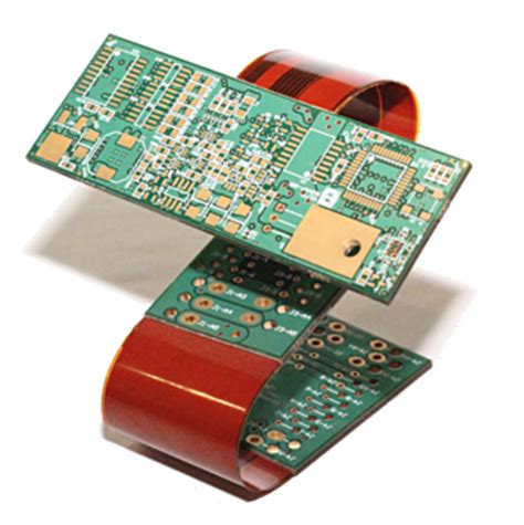
Flexible Printed Circuit Boards (Flexible PCBs) are a type of printed circuit board that can bend, twist, and fold without losing their electrical functionality. Unlike traditional rigid PCBs, flexible PCBs are made from thin, flexible materials such as polyimide or polyester films. This unique property allows them to be used in a wide range of applications where space is limited, or where the device needs to conform to a particular shape.
Flexible PCBs have been around since the 1950s, but their popularity has grown significantly in recent years due to the increasing demand for smaller, lighter, and more portable electronic devices. They are commonly used in consumer electronics, medical devices, aerospace, and automotive industries.
Advantages of Flexible PCB
Flexible PCBs offer several advantages over traditional rigid PCBs, including:
- Space savings: Flexible PCBs can be bent and folded to fit into tight spaces, reducing the overall size of the device.
- Weight reduction: Flexible PCBs are much lighter than rigid PCBs, making them ideal for portable devices.
- Increased reliability: Flexible PCBs are less likely to crack or break under stress, increasing the reliability of the device.
- Improved signal integrity: Flexible PCBs can be designed with shorter signal paths, reducing signal loss and improving signal integrity.
- Cost-effective: Flexible PCBs can reduce the overall cost of the device by eliminating the need for connectors and wires.
Types of Flexible PCB
There are three main types of flexible PCBs:
- Single-sided flexible PCBs: These PCBs have a single layer of conductive material on one side of the flexible substrate.
- Double-sided flexible PCBs: These PCBs have conductive material on both sides of the flexible substrate.
- Multi-layer flexible PCBs: These PCBs have three or more layers of conductive material, separated by insulating layers.
Single-Sided Flexible PCBs
Single-sided flexible PCBs are the simplest and most cost-effective type of flexible PCB. They consist of a single layer of conductive material, typically copper, on one side of a flexible substrate. The other side of the substrate is usually covered with a protective layer of insulating material.
Single-sided flexible PCBs are commonly used in applications where the circuit is relatively simple, and where cost is a primary concern. They are often used in consumer electronics, such as keyboards and remote controls.
Double-Sided Flexible PCBs
Double-sided flexible PCBs have conductive material on both sides of the flexible substrate. This allows for more complex circuits and higher component density than single-sided flexible PCBs.
Double-sided flexible PCBs are commonly used in applications where the circuit is more complex, and where space is at a premium. They are often used in medical devices, such as hearing aids and pacemakers.
Multi-Layer Flexible PCBs
Multi-layer flexible PCBs have three or more layers of conductive material, separated by insulating layers. This allows for even more complex circuits and higher component density than double-sided flexible PCBs.
Multi-layer flexible PCBs are commonly used in applications where the circuit is highly complex, and where space is extremely limited. They are often used in aerospace and military applications, such as satellites and missile systems.

Manufacturing Process of Flexible PCB
The manufacturing process of flexible PCBs is similar to that of rigid PCBs, but with some key differences. The basic steps in the manufacturing process are as follows:
- Substrate preparation: The flexible substrate, typically polyimide or polyester, is cleaned and treated to improve adhesion.
- Copper lamination: A thin layer of copper is laminated onto the substrate using heat and pressure.
- Photoresist application: A photoresist layer is applied to the copper layer and exposed to UV light through a photomask.
- Etching: The exposed copper is etched away using a chemical solution, leaving behind the desired circuit pattern.
- Protective coating: A protective coating, such as coverlay or solder mask, is applied to the circuit to protect it from damage.
- Cutting and drilling: The flexible PCB is cut to the desired size and shape, and any necessary holes are drilled.
- Surface finishing: The exposed copper is plated with a protective layer, such as gold or nickel, to improve durability and conductivity.
Key Differences in Manufacturing Process
The key differences in the manufacturing process of flexible PCBs compared to rigid PCBs are:
- Substrate material: Flexible PCBs use flexible substrates, such as polyimide or polyester, instead of the rigid FR-4 material used in rigid PCBs.
- Copper thickness: The copper layer in flexible PCBs is typically thinner than in rigid PCBs, to improve flexibility.
- Adhesive layer: An adhesive layer is often used to bond the copper layer to the substrate in flexible PCBs, to improve adhesion and prevent delamination.
- Coverlay: A protective coverlay layer is often used in flexible PCBs instead of the solder mask used in rigid PCBs, to improve flexibility and durability.

Applications of Flexible PCB
Flexible PCBs are used in a wide range of applications, including:
- Consumer electronics: Flexible PCBs are commonly used in smartphones, tablets, and wearable devices, where space is limited and the device needs to conform to the user’s body.
- Medical devices: Flexible PCBs are used in medical devices such as hearing aids, pacemakers, and insulin pumps, where reliability and durability are critical.
- Automotive: Flexible PCBs are used in automotive applications such as dashboard displays, sensors, and control modules, where vibration and temperature variations are common.
- Aerospace: Flexible PCBs are used in aerospace applications such as satellites, aircraft, and missiles, where weight and space are at a premium.
- Industrial: Flexible PCBs are used in industrial applications such as robotics, automation, and process control, where flexibility and durability are important.
Examples of Flexible PCB Applications
Here are some specific examples of flexible PCB applications:
- Smartphone camera modules: Flexible PCBs are used to connect the camera module to the main board in smartphones, allowing for a thinner and more compact design.
- Wearable fitness trackers: Flexible PCBs are used in wearable fitness trackers to conform to the user’s wrist and provide a comfortable fit.
- Hearing aids: Flexible PCBs are used in hearing aids to provide a compact and reliable solution for sound processing and amplification.
- Automotive sensors: Flexible PCBs are used in automotive sensors, such as tire pressure monitors and accelerometers, to provide a reliable and durable solution in harsh environments.
- Aerospace control modules: Flexible PCBs are used in aerospace control modules, such as flight control systems and engine control units, to provide a lightweight and reliable solution in extreme conditions.

Design Considerations for Flexible PCB
Designing a flexible PCB requires careful consideration of several factors, including:
- Bend radius: The minimum bend radius of the flexible PCB must be considered to ensure that the circuit can bend without breaking or causing damage.
- Copper thickness: The thickness of the copper layer must be carefully chosen to provide adequate conductivity while maintaining flexibility.
- Adhesive layer: The adhesive layer must be carefully selected to provide adequate bonding strength while maintaining flexibility.
- Coverlay: The coverlay material must be carefully selected to provide adequate protection and durability while maintaining flexibility.
- Component placement: The placement of components on the flexible PCB must be carefully considered to ensure that they can withstand the bending and flexing of the circuit.
Design Guidelines for Flexible PCB
Here are some general design guidelines for flexible PCBs:
- Avoid sharp bends: Sharp bends can cause stress on the copper traces and lead to cracking or breakage. Use gradual bends instead.
- Use tear-drop pads: Tear-drop pads can help to distribute stress and prevent cracking at the junction between the pad and the trace.
- Use strain relief: Strain relief features, such as slots or holes, can help to distribute stress and prevent damage to the circuit.
- Consider component placement: Place components away from the bend areas to minimize stress on the components and the circuit.
- Use appropriate materials: Choose materials that are appropriate for the application, considering factors such as temperature, humidity, and chemical exposure.
Advantages and Disadvantages of Flexible PCB
Flexible PCBs offer several advantages over traditional rigid PCBs, but they also have some disadvantages. Here are some of the main advantages and disadvantages of flexible PCBs:
Advantages
- Space savings: Flexible PCBs can be bent and folded to fit into tight spaces, reducing the overall size of the device.
- Weight reduction: Flexible PCBs are much lighter than rigid PCBs, making them ideal for portable devices.
- Increased reliability: Flexible PCBs are less likely to crack or break under stress, increasing the reliability of the device.
- Improved signal integrity: Flexible PCBs can be designed with shorter signal paths, reducing signal loss and improving signal integrity.
- Cost-effective: Flexible PCBs can reduce the overall cost of the device by eliminating the need for connectors and wires.
Disadvantages
- Higher cost: Flexible PCBs are generally more expensive than rigid PCBs due to the specialized materials and manufacturing processes required.
- Limited component options: The range of components that can be used on flexible PCBs is limited compared to rigid PCBs, due to the need for flexibility and the limited space available.
- Reduced power handling: Flexible PCBs have a lower power handling capacity than rigid PCBs due to the thinner copper layers and the need for flexibility.
- Reduced heat dissipation: Flexible PCBs have a lower heat dissipation capacity than rigid PCBs due to the thinner copper layers and the insulating properties of the substrate materials.
- Limited layer count: The number of layers that can be used in a flexible PCB is limited compared to rigid PCBs, due to the need for flexibility and the limited space available.
Future Trends in Flexible PCB
The demand for flexible PCBs is expected to continue to grow in the coming years, driven by the increasing demand for smaller, lighter, and more portable electronic devices. Here are some of the key trends that are expected to shape the future of flexible PCBs:
- Increased use of advanced materials: New materials, such as graphene and carbon nanotubes, are being developed that offer improved flexibility, conductivity, and durability compared to traditional materials.
- Continued miniaturization: The trend towards smaller and more compact electronic devices is expected to continue, driving the need for even smaller and more flexible PCBs.
- Increased use of 3D printing: 3D printing technology is being used to create flexible PCBs with complex shapes and structures that would be difficult or impossible to achieve with traditional manufacturing methods.
- Growing demand in emerging applications: Flexible PCBs are expected to find increasing use in emerging applications such as wearable devices, robotics, and the Internet of Things (IoT).
- Increased focus on sustainability: There is a growing focus on developing sustainable and environmentally friendly materials and manufacturing processes for flexible PCBs, to reduce their environmental impact.
Frequently Asked Questions (FAQ)
-
What is the difference between a flexible PCB and a rigid PCB?
A flexible PCB is made from a thin, flexible substrate material that allows it to bend and flex without breaking, while a rigid PCB is made from a rigid, non-flexible material such as FR-4. -
What are the advantages of using a flexible PCB?
Flexible PCBs offer several advantages over rigid PCBs, including space savings, weight reduction, increased reliability, improved signal integrity, and cost-effectiveness. -
What are the main applications of flexible PCBs?
Flexible PCBs are used in a wide range of applications, including consumer electronics, medical devices, automotive, aerospace, and industrial applications. -
What are the key design considerations for flexible PCBs?
The key design considerations for flexible PCBs include bend radius, copper thickness, adhesive layer, coverlay, and component placement. -
What are the future trends in flexible PCBs?
The future trends in flexible PCBs include increased use of advanced materials, continued miniaturization, increased use of 3D printing, growing demand in emerging applications, and increased focus on sustainability.
Conclusion
Flexible PCBs are a versatile and reliable solution for a wide range of electronic applications where space is limited, or where the device needs to conform to a particular shape. They offer several advantages over traditional rigid PCBs, including space savings, weight reduction, increased reliability, improved signal integrity, and cost-effectiveness.
The manufacturing process of flexible PCBs is similar to that of rigid PCBs, but with some key differences, such as the use of flexible substrate materials, thinner copper layers, and specialized adhesive and coverlay materials.
Designing a flexible PCB requires careful consideration of several factors, including bend radius, copper thickness, adhesive layer, coverlay, and component placement. Following general design guidelines, such as avoiding sharp bends and using strain relief features, can help to ensure the reliability and durability of the circuit.
The demand for flexible PCBs is expected to continue to grow in the coming years, driven by the increasing demand for smaller, lighter, and more portable electronic devices. Key trends that are expected to shape the future of flexible PCBs include the increased use of advanced materials, continued miniaturization, increased use of 3D printing, growing demand in emerging applications, and increased focus on sustainability.
| Type of Flexible PCB | Description | Typical Applications |
|---|---|---|
| Single-sided | Single layer of conductive material on one side of the substrate | Simple circuits, consumer electronics |
| Double-sided | Conductive material on both sides of the substrate | More complex circuits, medical devices |
| Multi-layer | Three or more layers of conductive material, separated by insulating layers | Highly complex circuits, aerospace and military applications |
No responses yet