Introduction to RF Baluns
In the world of radio frequency (RF) circuit design, a balun is an essential component that plays a crucial role in ensuring the proper operation and performance of many RF systems. The term “balun” is derived from the words “balanced” and “unbalanced,” which aptly describes its primary function. In this article, we will delve into the fundamentals of baluns, explore their various types and applications, and discuss whether your RF printed circuit board (PCB) requires one.
What is a Balun?
A balun is a passive electrical device that converts between balanced and unbalanced signals. It is commonly used in RF circuits to interface balanced transmission lines, such as twisted pair cables or balanced antennas, with unbalanced systems, such as coaxial cables or single-ended amplifiers. The balun ensures proper impedance matching, reduces electromagnetic interference (EMI), and maintains signal integrity.
The Need for Baluns in RF Circuits
In many RF applications, it is essential to maintain a balanced signal path to minimize unwanted radiation, reduce noise pickup, and improve overall system performance. However, most RF components, such as amplifiers, mixers, and filters, are designed to operate with unbalanced signals. This is where baluns come into play. They act as a bridge between balanced and unbalanced sections of the circuit, enabling seamless integration and optimal performance.
Types of RF Baluns
There are several types of baluns used in RF circuits, each with its own characteristics and applications. Let’s explore some of the most common types:
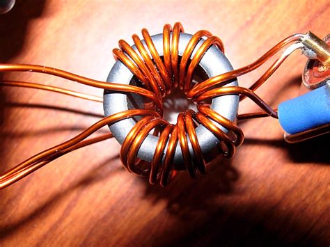
1. Transformer Baluns
Transformer baluns are the most basic and widely used type of balun. They consist of two or more coupled windings on a common magnetic core. The primary winding is connected to the unbalanced port, while the secondary winding is center-tapped to create a balanced output. Transformer baluns provide galvanic isolation, impedance transformation, and balanced-to-unbalanced conversion.
| Transformer Balun Properties | Description |
|---|---|
| Bandwidth | Moderate |
| Insertion Loss | Low to moderate |
| Power Handling | High |
| Size | Compact to large |
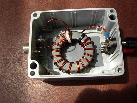
2. Transmission Line Baluns
Transmission line baluns, also known as coaxial baluns or choke baluns, are constructed using coaxial cables or twisted pair lines. They rely on the principle of common-mode current cancellation to achieve balanced-to-unbalanced conversion. Transmission line baluns are broadband, have low insertion loss, and are suitable for high-frequency applications.
| Transmission Line Balun Properties | Description |
|---|---|
| Bandwidth | Wide |
| Insertion Loss | Low |
| Power Handling | Moderate to high |
| Size | Compact |
3. Marchand Baluns
Marchand baluns are a type of transmission line balun that utilizes coupled transmission lines to achieve balanced-to-unbalanced conversion. They offer excellent bandwidth, low insertion loss, and good impedance matching. Marchand baluns are commonly used in microwave and millimeter-wave applications.
| Marchand Balun Properties | Description |
|---|---|
| Bandwidth | Very wide |
| Insertion Loss | Low |
| Power Handling | Moderate |
| Size | Compact |
4. Active Baluns
Active baluns incorporate active components, such as transistors or operational amplifiers, to perform balanced-to-unbalanced conversion. They offer the advantage of providing gain and impedance transformation in addition to balancing. Active baluns are useful in low-noise amplifier (LNA) designs and can be integrated into monolithic microwave integrated circuits (MMICs).
| Active Balun Properties | Description |
|---|---|
| Bandwidth | Moderate to wide |
| Insertion Loss | Gain possible |
| Power Handling | Low to moderate |
| Size | Compact |
Applications of RF Baluns
RF baluns find applications in various domains, including:
- Antennas: Baluns are used to interface balanced antennas, such as dipoles or loops, with unbalanced feedlines.
- Differential Amplifiers: Baluns are employed to convert single-ended signals to differential signals for driving differential amplifiers.
- Mixers: Baluns are used to provide balanced inputs or outputs for mixers, reducing even-order harmonics and improving linearity.
- Phase Shifters: Baluns can be used in conjunction with phase shifters to achieve balanced phase shifting.
- Power Combiners/Dividers: Baluns are utilized in power combining or dividing networks to maintain balance and minimize loss.

Designing with RF Baluns
When incorporating baluns into your RF PCB design, consider the following factors:
- Frequency Range: Select a balun that covers the desired frequency range of your application.
- Impedance Matching: Ensure proper impedance matching between the balun and the connected components to minimize reflections and optimize power transfer.
- Power Handling: Choose a balun with sufficient power handling capability to accommodate the expected signal levels.
- Insertion Loss: Minimize insertion loss by selecting a balun with low loss characteristics and optimizing the PCB layout.
- PCB Layout: Follow best practices for RF PCB layout, such as minimizing trace lengths, avoiding sharp bends, and providing proper grounding.
Does Your RF PCB Need a Balun?
The decision to include a balun in your RF PCB depends on several factors:
- Signal Integrity: If your design requires a balanced signal path to maintain signal integrity and reduce noise, a balun is necessary.
- Impedance Matching: If you need to interface balanced and unbalanced components with different impedances, a balun can provide the required impedance transformation.
- EMI Reduction: Baluns can help reduce electromagnetic interference by canceling common-mode currents and minimizing radiation.
- System Requirements: Consider the specific requirements of your RF system, such as frequency range, power levels, and performance targets, to determine if a balun is beneficial.
In many cases, incorporating a balun in your RF PCB design can significantly improve system performance, reduce noise, and ensure proper operation. However, it’s essential to carefully evaluate your specific application and consult with experienced RF engineers to make an informed decision.
Frequently Asked Questions (FAQ)
1. What is the primary function of a balun in an RF circuit?
A: The primary function of a balun in an RF circuit is to convert between balanced and unbalanced signals. It interfaces balanced transmission lines or components with unbalanced systems, ensuring proper impedance matching and reducing electromagnetic interference.
2. Can a balun provide impedance transformation?
A: Yes, many types of baluns, such as transformer baluns and active baluns, can provide impedance transformation in addition to balanced-to-unbalanced conversion. This allows for proper impedance matching between components with different characteristic impedances.
3. Are baluns frequency-dependent?
A: Yes, baluns are frequency-dependent devices. Each type of balun has a specific frequency range over which it operates effectively. It’s important to select a balun that covers the desired frequency range of your application to ensure optimal performance.
4. How do I choose the right balun for my RF PCB?
A: When choosing a balun for your RF PCB, consider factors such as the frequency range, impedance matching requirements, power handling capability, insertion loss, and system requirements. Consult datasheets, application notes, and seek guidance from experienced RF engineers to make an informed decision.
5. Can I design my own balun for my RF PCB?
A: Yes, it is possible to design your own balun for your RF PCB. However, designing a high-performance balun requires expertise in RF circuit design, electromagnetic simulations, and PCB layout techniques. If you have the necessary skills and resources, you can create custom baluns tailored to your specific application requirements.
Conclusion
Baluns are indispensable components in many RF circuits, enabling the interface between balanced and unbalanced systems while ensuring signal integrity and reducing electromagnetic interference. Understanding the different types of baluns, their applications, and design considerations is crucial for successful RF PCB design.
When deciding whether your RF PCB needs a balun, carefully evaluate your system requirements, signal integrity concerns, and impedance matching needs. By incorporating the right balun in your design and following best practices for RF PCB layout, you can achieve optimal performance and reliability in your RF applications.
Remember to consult with experienced RF engineers, refer to application notes and datasheets, and perform thorough simulations and testing to validate your balun selection and design. With a solid understanding of baluns and their role in RF circuits, you can unlock the full potential of your RF PCB and build robust, high-performance systems.
No responses yet