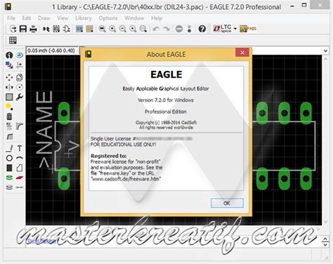
Introduction to CadSoft EAGLE V7
CadSoft EAGLE V7 is a powerful and versatile Electronic design automation (EDA) software that has revolutionized the way engineers and hobbyists design printed circuit boards (PCBs). With its user-friendly interface, extensive libraries, and advanced features, EAGLE V7 has become a go-to choice for professionals and enthusiasts alike. In this article, we will dive deep into the world of CadSoft EAGLE V7, exploring its features, benefits, and how it can streamline your PCB design process.
What is CadSoft EAGLE V7?
CadSoft EAGLE V7 is a comprehensive EDA software package that enables users to design and layout PCBs efficiently. It offers a complete solution for schematic capture, board layout, and manufacturing output generation. EAGLE V7 is known for its intuitive interface, which allows users to quickly learn and navigate the software, even if they have limited experience in PCB design.
Key Features of CadSoft EAGLE V7
-
Schematic Editor: EAGLE V7 provides a powerful schematic editor that allows users to create, edit, and organize electronic schematics easily. It supports hierarchical designs, making it suitable for both simple and complex projects.
-
Board Layout Editor: The board layout editor in EAGLE V7 offers a wide range of tools and features to design PCBs efficiently. It supports multi-layer boards, automatic routing, and real-time design rule checking (DRC) to ensure your designs are error-free.
-
Extensive Libraries: EAGLE V7 comes with an extensive collection of libraries that include components from various manufacturers. These libraries can be easily customized and expanded to suit your specific design needs.
-
3D Visualization: EAGLE V7 offers 3D visualization capabilities, allowing you to view your PCB designs in a realistic 3D environment. This feature helps in identifying potential issues and optimizing your designs before manufacturing.
-
Flexible Output Generation: With EAGLE V7, you can generate a wide range of output files, including Gerber Files, drill files, and pick-and-place files, which are essential for PCB manufacturing.
Getting Started with CadSoft EAGLE V7
System Requirements
Before installing CadSoft EAGLE V7, ensure that your system meets the following minimum requirements:
| Operating System | Processor | RAM | Hard Disk Space |
|---|---|---|---|
| Windows 7/8/10 | 1 GHz | 2 GB | 500 MB |
| macOS 10.11+ | Intel | 2 GB | 500 MB |
| Linux | 1 GHz | 2 GB | 500 MB |
Installation Process
Installing CadSoft EAGLE V7 is a straightforward process. Follow these steps to get started:
- Download the EAGLE V7 installer from the official CadSoft website or Rayming’s website.
- Run the installer and follow the on-screen instructions.
- Choose the installation directory and select the components you want to install.
- Complete the installation process and launch EAGLE V7.
Licensing Options
CadSoft EAGLE V7 offers various licensing options to cater to different user needs:
- Freeware Version: The freeware version is suitable for non-commercial use and has limitations on board size and number of layers.
- Standard License: The standard license unlocks additional features and removes the limitations of the freeware version. It is suitable for individual designers and small businesses.
- Premium License: The premium license offers the full range of EAGLE V7 features and is ideal for professional users and large organizations.

EAGLE V7 User Interface
Main Window
The main window of EAGLE V7 consists of several key areas:
- Menu Bar: The menu bar provides access to various commands and tools.
- Toolbar: The toolbar contains frequently used tools and commands for quick access.
- Control Panel: The control panel displays the libraries, design rules, and other project-related information.
- Editor Window: The editor window is where you create and edit your schematics and board layouts.
Customizing the Interface
EAGLE V7 allows you to customize the user interface to suit your preferences:
- Changing Theme: You can change the color scheme of the interface by selecting a different theme from the Options menu.
- Customizing Toolbars: You can add, remove, or rearrange tools in the toolbar by right-clicking on the toolbar and selecting “Customize.”
- Keyboard Shortcuts: EAGLE V7 supports a wide range of keyboard shortcuts to speed up your workflow. You can view and modify these shortcuts in the “Options” dialog.

Creating a New Project
Project Wizard
EAGLE V7 offers a Project Wizard that guides you through the process of creating a new project:
- Select “File” > “New” > “Project” from the menu bar.
- Choose a project name and location.
- Select the schematic and board files you want to include in the project.
- Click “Finish” to create the project.
Creating a Schematic
To create a new schematic in EAGLE V7:
- Select “File” > “New” > “Schematic” from the menu bar.
- Use the schematic editor to add components, draw wires, and create connections.
- Assign unique names to components and nets for easy identification.
- Validate the schematic using the Electrical Rule Check (ERC) tool.
Creating a Board Layout
Once you have created a schematic, you can generate a board layout:
- Select “File” > “Switch to Board” from the menu bar.
- Use the board layout editor to place components and route traces.
- Define the board outline and apply design rules.
- Perform a Design Rule Check (DRC) to ensure your layout meets the specified rules.

Libraries and Components
Using Existing Libraries
EAGLE V7 comes with an extensive collection of libraries that include components from various manufacturers. To use a component from an existing library:
- Open the Control Panel and navigate to the “Libraries” tab.
- Locate the desired library and expand it to view the available components.
- Drag and drop the component into your schematic or board layout.
Creating Custom Libraries
You can create your own custom libraries in EAGLE V7 to store frequently used components or custom designs:
- Select “File” > “New” > “Library” from the menu bar.
- Use the library editor to create new components or modify existing ones.
- Define the component’s symbol, package, and device.
- Save the library and add it to your projects as needed.
Routing and Autorouting
Manual Routing
Manual routing allows you to have full control over the placement of traces on your PCB. To manually route traces:
- Select the “Route” tool from the toolbar.
- Click on the starting point of the trace and move the cursor to the desired endpoint.
- Use the various routing options, such as changing layer or width, to optimize your traces.
- Repeat the process for all the connections in your design.
Autorouting
Autorouting is a powerful feature in EAGLE V7 that automatically routes traces based on predefined design rules. To use autorouting:
- Define the design rules for your project, including trace width, clearance, and via size.
- Select the “Auto” tool from the toolbar.
- Configure the autorouter settings, such as routing strategy and optimization level.
- Run the autorouter and review the results.
- Make manual adjustments as needed to optimize the routing.
Design Rule Check (DRC)
Running a DRC
The Design Rule Check (DRC) is an essential step in ensuring the integrity of your PCB design. To run a DRC:
- Select “Tools” > “DRC” from the menu bar.
- Configure the DRC settings, such as clearance, width, and drill size.
- Click “Check” to start the DRC process.
- Review the DRC report and address any violations.
Customizing DRC Rules
You can customize the DRC rules to match your specific manufacturing requirements:
- Open the “DRC” dialog and click on the “Rules” tab.
- Create new rules or modify existing ones based on your needs.
- Specify the layer, width, clearance, and other parameters for each rule.
- Apply the rules to your design and run the DRC to ensure compliance.
Manufacturing Output
Generating Gerber Files
Gerber files are the industry standard for PCB manufacturing. To generate Gerber files in EAGLE V7:
- Select “File” > “CAM Processor” from the menu bar.
- Load the appropriate CAM job file for your manufacturing requirements.
- Configure the output settings, such as file format and resolution.
- Generate the Gerber files and review them using a Gerber Viewer.
Generating Drill Files
Drill files contain information about the holes and vias in your PCB design. To generate drill files:
- Open the “CAM Processor” and load the appropriate drill job file.
- Configure the output settings, such as drill units and Hole Sizes.
- Generate the drill files and review them using a drill file viewer.
Generating Pick-and-Place Files
Pick-and-place files provide information for automated assembly machines. To generate pick-and-place files:
- Open the “CAM Processor” and load the appropriate pick-and-place job file.
- Configure the output settings, such as file format and component orientation.
- Generate the pick-and-place files and review them using a text editor or spreadsheet software.
Frequently Asked Questions (FAQ)
- What is the difference between the freeware and licensed versions of EAGLE V7?
-
The freeware version of EAGLE V7 is suitable for non-commercial use and has limitations on board size and number of layers. The licensed versions (Standard and Premium) remove these limitations and offer additional features and support.
-
Can I import designs from other EDA software into EAGLE V7?
-
Yes, EAGLE V7 supports importing designs from various file formats, including Altium Designer, OrCAD, and KiCad. You can use the “File” > “Import” command to bring your designs into EAGLE V7.
-
How can I share my EAGLE V7 designs with others?
-
You can share your EAGLE V7 designs by exporting them as a project bundle. Select “File” > “Export” > “Project” to create a single file containing all the necessary schematic, board, and library files. Others can then import this project bundle into their EAGLE V7 installation.
-
What resources are available for learning EAGLE V7?
-
CadSoft offers extensive documentation, tutorials, and video guides on their website to help users learn EAGLE V7. Additionally, there are numerous online forums, communities, and third-party tutorials that provide valuable insights and tips for mastering EAGLE V7.
-
How can I get support for EAGLE V7?
- CadSoft provides technical support for licensed users of EAGLE V7. You can contact their support team through email or the official support portal. Freeware users can seek assistance from the EAGLE community forums and online resources.
Conclusion
CadSoft EAGLE V7 is a powerful and user-friendly EDA software that simplifies the process of designing and laying out PCBs. With its intuitive interface, extensive libraries, and advanced features, EAGLE V7 caters to the needs of both beginners and experienced designers. By following the tips and techniques outlined in this article, you can harness the full potential of EAGLE V7 and create professional-grade PCB designs efficiently.
Whether you are a hobbyist working on personal projects or a professional designer dealing with complex layouts, CadSoft EAGLE V7 provides the tools and flexibility to bring your ideas to life. So, dive into the world of EAGLE V7, explore its capabilities, and unlock your creativity in PCB design.
No responses yet