Introduction to Voltage-Current Indication
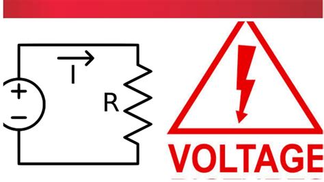
Voltage and current are two fundamental concepts in electrical engineering that are essential for understanding the behavior of electrical circuits. Voltage is the potential difference between two points in a circuit, while current is the flow of electric charge through a conductor. The relationship between voltage and current is described by Ohm’s law, which states that the current through a conductor is directly proportional to the voltage across it, and inversely proportional to the resistance of the conductor.
Voltage-current indication is a crucial aspect of electrical circuit analysis and design. It involves representing the voltage and current distribution in a circuit using visual aids such as voltage contour maps and current direction arrows. These tools help engineers and technicians to better understand the behavior of a circuit and identify potential issues such as short circuits, open circuits, and voltage drops.
Importance of Voltage-Current Indication
Voltage-current indication is important for several reasons:
-
Circuit Analysis: Voltage-current indication helps in analyzing the behavior of electrical circuits. By representing the voltage and current distribution in a circuit using visual aids, engineers can identify potential issues such as short circuits, open circuits, and voltage drops.
-
Circuit Design: Voltage-current indication is also useful in circuit design. By representing the voltage and current distribution in a circuit, engineers can optimize the circuit design to minimize power losses and ensure proper functioning of the circuit components.
-
Troubleshooting: Voltage-current indication is a valuable tool for troubleshooting electrical circuits. By visualizing the voltage and current distribution in a circuit, technicians can identify the location and cause of faults in the circuit.
Voltage Contour Maps
A voltage contour map is a visual representation of the voltage distribution in an electrical circuit. It is created by measuring the voltage at various points in the circuit and plotting the results on a graph. The resulting graph shows the voltage level at each point in the circuit, with different colors or shades representing different voltage levels.
Creating a Voltage Contour Map
To create a voltage contour map, follow these steps:
-
Measure the Voltage: Use a voltmeter to measure the voltage at various points in the circuit. Record the voltage readings and the corresponding locations in the circuit.
-
Plot the Results: Plot the voltage readings on a graph, with the x-axis representing the distance along the circuit and the y-axis representing the voltage level. Use different colors or shades to represent different voltage levels.
-
Interpolate the Results: Interpolate the voltage readings between the measured points to create a smooth contour map. This can be done using software tools or by hand.
-
Analyze the Map: Analyze the voltage contour map to identify potential issues such as voltage drops, short circuits, and open circuits. Look for areas of high or low voltage, as well as sudden changes in voltage level.
Example of a Voltage Contour Map
Here is an example of a voltage contour map for a simple resistive circuit:
| Distance (cm) | Voltage (V) |
|---|---|
| 0 | 10 |
| 1 | 9.5 |
| 2 | 9 |
| 3 | 8.5 |
| 4 | 8 |
| 5 | 7.5 |
| 6 | 7 |
| 7 | 6.5 |
| 8 | 6 |
| 9 | 5.5 |
| 10 | 5 |
In this example, the voltage drops uniformly along the length of the resistor, from 10V at one end to 5V at the other end. The voltage contour map shows this voltage drop as a smooth gradient from red (high voltage) to blue (low voltage).
Current Direction Arrows
Current direction arrows are used to indicate the direction of current flow in an electrical circuit. They are typically drawn on a circuit diagram, with the arrow pointing in the direction of conventional current flow (from positive to negative).
Drawing Current Direction Arrows
To draw current direction arrows on a circuit diagram, follow these steps:
-
Identify the Current Path: Identify the path that current will take through the circuit. Current flows from the positive terminal of the voltage source, through the circuit components, and back to the negative terminal of the voltage source.
-
Determine the Direction of Current Flow: Determine the direction of current flow based on the polarity of the voltage source and the arrangement of the circuit components. Conventional current flows from positive to negative.
-
Draw the Arrows: Draw arrows on the circuit diagram to indicate the direction of current flow. The arrows should point in the direction of conventional current flow, with the arrowhead pointing towards the negative terminal of the voltage source.
-
Label the Arrows: Label the arrows with the appropriate current values, if known. This can help in analyzing the behavior of the circuit and identifying potential issues.
Example of Current Direction Arrows
Here is an example of current direction arrows on a simple resistive circuit:
   +---R1---+
   |        |
+--+        +--R2--+
|                  |
V                  |
|                  |
+------------------+
In this example, current flows from the positive terminal of the voltage source (V), through resistor R1, then through resistor R2, and finally back to the negative terminal of the voltage source. The current direction arrows indicate this flow, with the arrowheads pointing towards the negative terminal of the voltage source.

Combining Voltage Contour Maps and Current Direction Arrows
Voltage contour maps and current direction arrows can be combined to provide a complete picture of the voltage and current distribution in an electrical circuit. By overlaying the current direction arrows on top of the voltage contour map, engineers can visualize the relationship between voltage and current in the circuit.
Example of Combined Voltage Contour Map and Current Direction Arrows
Here is an example of a combined voltage contour map and current direction arrows for a simple resistive circuit:
   +---R1---+
   |        |
+--+        +--R2--+
|    +--->         |
V   +---+          |
|   |   |          |
+---+   +----------+
In this example, the voltage contour map shows the voltage drop across resistors R1 and R2, while the current direction arrows indicate the direction of current flow through the circuit. By combining these two visual aids, engineers can quickly identify potential issues such as voltage drops and open circuits.

FAQ
-
What is the difference between voltage and current?
Voltage is the potential difference between two points in a circuit, while current is the flow of electric charge through a conductor. -
What is Ohm’s law?
Ohm’s law states that the current through a conductor is directly proportional to the voltage across it, and inversely proportional to the resistance of the conductor. -
What is a voltage contour map?
A voltage contour map is a visual representation of the voltage distribution in an electrical circuit, created by measuring the voltage at various points in the circuit and plotting the results on a graph. -
What are current direction arrows?
Current direction arrows are used to indicate the direction of current flow in an electrical circuit, and are typically drawn on a circuit diagram with the arrow pointing in the direction of conventional current flow. -
How can voltage contour maps and current direction arrows be combined?
Voltage contour maps and current direction arrows can be combined by overlaying the current direction arrows on top of the voltage contour map, providing a complete picture of the voltage and current distribution in an electrical circuit.
Conclusion
Voltage-current indication is a crucial aspect of electrical circuit analysis and design. By using visual aids such as voltage contour maps and current direction arrows, engineers can better understand the behavior of a circuit and identify potential issues. Voltage contour maps provide a graphical representation of the voltage distribution in a circuit, while current direction arrows indicate the direction of current flow. By combining these two tools, engineers can quickly identify potential issues such as voltage drops, short circuits, and open circuits. Overall, voltage-current indication is an essential skill for any electrical engineer or technician, and mastering it can lead to more efficient and effective circuit design and troubleshooting.
No responses yet