What is a Voltage Comparator?
A voltage comparator is an electronic circuit that compares two voltages and outputs a digital signal indicating which voltage is larger. It is a fundamental building block in analog circuits and is used in a wide variety of applications, such as analog-to-digital converters (ADCs), pulse width modulators (PWMs), and voltage level detectors.
The basic operation of a voltage comparator is as follows: it has two analog input voltages, called the reference voltage (Vref) and the input voltage (Vin). The comparator compares these two voltages and outputs a digital signal (Vout) based on the comparison. If Vin is greater than Vref, the output is a logic high (usually the positive supply voltage), and if Vin is less than Vref, the output is a logic low (usually the negative supply voltage or ground).
| Input Condition | Output |
|---|---|
| Vin > Vref | High |
| Vin < Vref | Low |
Ideal vs. Practical Voltage Comparators
An ideal voltage comparator would have the following characteristics:
- Infinite gain
- Infinite Input impedance
- Zero output impedance
- Zero Propagation Delay
- Infinite bandwidth
- Zero offset voltage
However, practical voltage comparators have limitations and non-ideal characteristics that must be considered when designing circuits.
Key Parameters of Voltage Comparators
- Input offset voltage: The voltage difference between the two inputs that causes the output to change states when both inputs are equal.
- Propagation delay: The time taken for the output to change states after the input voltage difference crosses the threshold.
- Slew rate: The maximum rate of change of the output voltage.
- Gain: The ratio of the output voltage change to the input voltage difference.
- Input impedance: The resistance between the input terminals of the comparator.
- Output impedance: The resistance between the output terminal and ground.
Types of Voltage Comparators
Open-Collector Comparators
Open-collector comparators have an output stage that consists of a transistor with an open collector. This allows the output to be connected to a pull-up resistor, enabling it to interface with different voltage levels or to be connected to other open-collector outputs for performing logical operations.
Push-Pull Comparators
Push-pull comparators have an output stage that consists of both an NPN and a PNP transistor, allowing the output to source or sink current. This type of output is useful when driving loads directly, such as LEDs or small relays.
Rail-to-Rail Comparators
Rail-to-rail comparators have input and output stages that can operate close to the positive and negative supply voltages. This is useful in low-voltage applications where it is necessary to maximize the usable input and output voltage range.
Applications of Voltage Comparators
Analog-to-Digital Converters (ADCs)
Voltage comparators are used in ADCs to compare the input voltage with a reference voltage generated by a digital-to-analog converter (DAC). The comparator output is then used by the ADC’s control logic to determine the digital representation of the input voltage.
Pulse Width Modulators (PWMs)
In PWM applications, a voltage comparator is used to compare a reference voltage with a sawtooth or triangular waveform. The output of the comparator is a pulse-width modulated signal, where the duty cycle is proportional to the reference voltage.
Window Comparators
Window comparators are used to determine if an input voltage lies within a specified range. They consist of two comparators with different reference voltages, and the output is high only when the input voltage is between the two reference voltages.
Zero-Crossing Detectors
Zero-crossing detectors are used to detect when an AC signal crosses zero volts. This is useful in power control applications, such as phase-angle control of AC loads.

Comparator Circuit Design Considerations
When designing circuits using voltage comparators, several factors must be considered to ensure proper operation:
- Input voltage range: The input voltage range of the comparator must be compatible with the expected range of input voltages.
- Output voltage range: The output voltage range of the comparator must be compatible with the requirements of the load or the next stage in the circuit.
- Power supply requirements: The comparator must be powered by a supply voltage that is within its specified operating range.
- Hysteresis: Hysteresis can be added to a comparator circuit to prevent output oscillation when the input voltage is close to the reference voltage.
- Response time: The propagation delay and slew rate of the comparator must be fast enough for the intended application.
Comparator ICs
There are many integrated circuit (IC) voltage comparators available, each with different specifications and features. Some popular comparator ICs include:
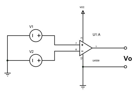
- LM339: A quad comparator with open-collector outputs.
- LM393: A dual comparator with open-collector outputs.
- LM311: A single comparator with a strobe input and a transistor output.
- TL331: A single comparator with a push-pull output and a latch input.
- MAX942: A single comparator with a rail-to-rail input and output, and a low propagation delay.
Comparator Circuit Examples
Simple Comparator Circuit
A simple comparator circuit consists of a comparator IC, a reference voltage source, and a pull-up resistor for the output. The reference voltage can be generated using a voltage divider or a dedicated voltage reference IC.
Window Comparator Circuit
A window comparator circuit consists of two comparators with different reference voltages, and an AND gate that combines their outputs. The output of the AND gate is high only when the input voltage is between the two reference voltages.
Hysteresis Comparator Circuit
A hysteresis comparator circuit adds positive feedback to a comparator to create a Schmitt trigger. This introduces hysteresis, which prevents output oscillation when the input voltage is close to the reference voltage. The amount of hysteresis is determined by the ratio of the feedback resistors.
Frequently Asked Questions
- What is the difference between a voltage comparator and an operational amplifier (op-amp)?
-
A voltage comparator is designed to compare two voltages and output a digital signal indicating which voltage is larger. An op-amp, on the other hand, is designed to amplify the difference between its two input voltages.
-
Can a voltage comparator be used as an op-amp?
-
While a voltage comparator can be used as a crude op-amp in some applications, it is not recommended because comparators are optimized for fast switching and may have poor linearity and gain characteristics.
-
What is the purpose of hysteresis in a comparator circuit?
-
Hysteresis is used to prevent output oscillation when the input voltage is close to the reference voltage. It introduces a difference between the voltage thresholds for the output to switch from low to high and from high to low, effectively creating a “dead band” where the output does not change state.
-
How do I choose the appropriate comparator IC for my application?
-
When selecting a comparator IC, consider the required input and output voltage ranges, power supply requirements, speed (propagation delay and slew rate), and any additional features such as open-collector outputs or rail-to-rail inputs and outputs.
-
Can I use a comparator to compare two AC signals?
- Yes, a comparator can be used to compare two AC signals by first converting them to DC voltages using rectifiers or Peak Detectors. The resulting DC voltages can then be compared using a standard comparator circuit.
In conclusion, voltage comparators are essential building blocks in analog circuit design, with a wide range of applications in signal processing, power control, and data conversion. By understanding the key parameters and characteristics of comparators, as well as the various types and circuit configurations available, designers can effectively incorporate these versatile devices into their projects.
No responses yet