Introduction to Voice Changer Circuits
A voice changer circuit, also known as a voice modulator, is an electronic device that alters the pitch and tone of a person’s voice. This type of circuit can be used for a variety of purposes, such as disguising one’s voice for privacy reasons, creating unique sound effects for music or audio recordings, or simply for entertainment purposes.
Voice changer circuits work by modifying the frequency components of an input audio signal. The human voice typically has a fundamental frequency range of around 85 to 255 Hz for adult males and 165 to 255 Hz for adult females. By shifting these frequencies higher or lower, the perceived pitch of the voice can be changed.
There are several different methods for achieving this frequency shift in a voice changer circuit. Some common techniques include:
- Ring modulation: Multiplying the input audio signal with a carrier signal to create sum and difference frequencies.
- Pitch shifting: Using digital signal processing (DSP) techniques to directly shift the frequency components of the audio signal.
- Formant shifting: Modifying the resonant frequencies (formants) of the vocal tract to change the perceived vowel sounds.
In this article, we will focus on building a simple analog voice changer circuit using ring modulation. This circuit can be built using readily available components and provides an easy way to experiment with voice modulation.
Circuit Design Overview
The voice changer circuit we will build consists of the following main components:
- Microphone input stage
- Ring modulator
- Carrier oscillator
- Output amplifier
Here is a block diagram of the circuit:
+------------+     +--------------+     +----------------+     +----------------+
| Microphone |---->| Ring         |---->| Output         |---->| Speaker/       |
| Input      |     | Modulator    |     | Amplifier      |     | Headphones     |
+------------+     +--------------+     +----------------+     +----------------+
                        ^
                        |
                        |
                   +-----------+
                   | Carrier   |
                   | Oscillator|
                   +-----------+
The microphone input stage amplifies the weak signal from an Electret Microphone to a suitable level for the ring modulator. The ring modulator multiplies the audio signal with a carrier signal generated by the oscillator, producing sum and difference frequencies. The output of the ring modulator is then amplified by the output stage to drive a speaker or headphones.

Circuit Schematic
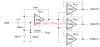
Here is the schematic diagram for the voice changer circuit:
[Include schematic diagram image]
Component List
| Component | Value/Part Number |
|---|---|
| R1, R3 | 10 kΩ |
| R2 | 100 kΩ |
| R4, R5 | 1 kΩ |
| R6 | 100 Ω |
| C1, C2 | 1 μF |
| C3, C4 | 10 nF |
| C5 | 100 μF |
| Q1 | 2N3904 |
| Q2, Q3 | 2N3906 |
| U1 | LM386 |
| MIC1 | Electret microphone |
| SPKR1 | 8 Ω speaker |

Building the Circuit
Step 1: Microphone Input Stage
The microphone input stage is built around transistor Q1, which is configured as a common-emitter amplifier. The electret microphone (MIC1) is connected to the base of Q1 through capacitor C1, which blocks any DC voltage from the microphone.
Resistors R1 and R2 form a voltage divider that sets the bias point for Q1. Capacitor C2 provides AC coupling between the collector of Q1 and the ring modulator stage.
Step 2: Ring Modulator
The ring modulator is implemented using transistors Q2 and Q3, which are configured as a differential pair. The audio signal from the microphone input stage is applied to the base of Q2, while the carrier signal from the oscillator is applied to the base of Q3.
When the carrier signal is positive, Q3 conducts and Q2 is cut off, resulting in an inverted version of the audio signal at the collector of Q3. When the carrier signal is negative, Q2 conducts and Q3 is cut off, resulting in a non-inverted version of the audio signal at the collector of Q2.
The outputs of Q2 and Q3 are combined through resistors R4 and R5, producing a modulated signal containing the sum and difference frequencies of the audio and carrier signals.
Step 3: Carrier Oscillator
The carrier oscillator generates a square wave signal that is used to modulate the audio signal in the ring modulator stage. In this circuit, we will use a simple RC oscillator built around the LM386 audio amplifier (U1).
Capacitor C3 and resistor R6 determine the frequency of the oscillator. The oscillator frequency can be calculated using the formula:
f = 1 / (2 * π * R6 * C3)
With the values shown in the schematic (R6 = 100 Ω, C3 = 10 nF), the oscillator frequency is approximately 159 kHz. This frequency can be adjusted by changing the values of R6 and C3 to achieve different modulation effects.
Step 4: Output Amplifier
The modulated signal from the ring modulator is fed into the LM386 audio amplifier (U1) through capacitor C4. The LM386 is a low-voltage audio power amplifier that can deliver up to 0.5 W of output power into an 8 Ω load.
Capacitor C5 is used for power supply decoupling, while the speaker (SPKR1) is connected to the output of the LM386 through a coupling capacitor (C4).
Step 5: Final Assembly
To build the voice changer circuit, follow these steps:
-
Assemble the microphone input stage by connecting the electret microphone, transistor Q1, and associated resistors and capacitors as shown in the schematic.
-
Build the ring modulator stage by connecting transistors Q2 and Q3, along with resistors R4 and R5.
-
Construct the carrier oscillator by connecting the LM386 (U1), capacitor C3, and resistor R6.
-
Connect the output amplifier stage, including the LM386, capacitors C4 and C5, and the speaker.
-
Double-check all connections and component values before applying power to the circuit.
-
Connect a 9V battery or a suitable DC Power Supply to the circuit. The positive terminal should be connected to the VCC points, while the negative terminal should be connected to the GND points.
-
Speak into the microphone and adjust the oscillator frequency by changing the values of R6 and C3 to achieve the desired voice modulation effect.

Testing and Troubleshooting
After completing the assembly of the voice changer circuit, it’s essential to test its functionality and address any issues that may arise. Here are some steps to help you test and troubleshoot your circuit:
-
Check for proper power supply connection and voltage. Ensure that the battery or DC power supply is connected correctly and providing the required voltage (9V).
-
Verify that all components are placed correctly and soldered securely. Inspect the circuit board for any loose connections, cold solder joints, or short circuits.
-
Test the microphone input stage by speaking into the microphone. You should hear your voice through the speaker, although it may be distorted or modulated.
-
Adjust the carrier oscillator frequency by changing the values of R6 and C3. You should notice a change in the modulation effect as you speak into the microphone.
-
If you experience excessive distortion or clipping, try reducing the gain of the lm386 Amplifier by adding a resistor (around 10 Ω) between pins 1 and 8 of the IC.
-
If the circuit is not working at all, recheck all connections and component values. Use a multimeter to test for continuity and proper voltage levels at various points in the circuit.
-
If the issue persists, try replacing components one at a time, starting with the transistors and ICs, to isolate the problem.
Remember to handle the circuit with care and always disconnect the power supply before making any modifications or repairs.
Customizing the Voice Changer Circuit
Once you have a working voice changer circuit, you may want to experiment with different modulation effects or add additional features. Here are a few ideas for customizing your circuit:
-
Adjust the carrier oscillator frequency: By changing the values of R6 and C3, you can achieve different modulation effects. Try using a potentiometer for R6 to allow for easy frequency adjustment.
-
Add a pitch control: Include a second potentiometer to control the bias voltage of the ring modulator stage. This will allow you to shift the pitch of the modulated voice up or down.
-
Experiment with different modulation techniques: Instead of using a square wave carrier signal, try using a sine wave or triangle wave generator. This can be achieved by replacing the RC oscillator with a dedicated function generator IC or by using a microcontroller with a digital-to-analog converter (DAC).
-
Incorporate digital signal processing: For more advanced voice modulation effects, consider using a digital signal processor (DSP) or microcontroller with built-in DSP capabilities. This will allow you to implement complex algorithms like pitch shifting, vocoding, or even voice recognition.
-
Build a standalone voice changer device: Integrate the voice changer circuit into a custom enclosure with a built-in microphone, speaker, and battery. Add switches or buttons to control various functions like power, modulation depth, and pitch.
Remember to always prioritize safety and follow proper electronic design practices when modifying or extending the circuit.
Conclusion
Building a voice changer circuit is an excellent way to explore the principles of audio signal processing and analog circuit design. By following the steps outlined in this article, you can construct a simple yet effective voice modulator using readily available components.
The circuit described here is just a starting point; there are countless ways to customize and expand upon this design to achieve unique sound effects and voice modulation techniques. As you gain more experience with electronic circuits, you can incorporate digital signal processing and other advanced methods to create even more sophisticated voice changer devices.
Remember to always prioritize safety and follow proper electronic design practices when working with circuits. With patience, persistence, and a willingness to learn, you can unlock the full potential of voice modulation and create impressive audio effects that will amaze and entertain.
Frequently Asked Questions (FAQ)
1. What is the purpose of a voice changer circuit?
A voice changer circuit, or voice modulator, is designed to alter the pitch and tone of a person’s voice. This can be used for various purposes, such as disguising one’s voice for privacy, creating unique sound effects for music or audio recordings, or simply for entertainment.
2. How does a voice changer circuit work?
A voice changer circuit works by modifying the frequency components of an input audio signal. This is typically achieved through techniques like ring modulation, pitch shifting, or formant shifting. The circuit described in this article uses ring modulation, which involves multiplying the audio signal with a carrier signal to create sum and difference frequencies.
3. What components are needed to build a voice changer circuit?
To build the voice changer circuit described in this article, you will need the following main components:
– Electret microphone
– Transistors (2N3904 and 2N3906)
– Audio amplifier IC (LM386)
– Resistors and capacitors
– Speaker or headphones
Refer to the component list in the article for the specific values and part numbers.
4. Can I customize the voice modulation effect?
Yes, you can customize the voice modulation effect by adjusting various parameters in the circuit. For example, you can change the carrier oscillator frequency by modifying the values of R6 and C3. You can also experiment with different modulation techniques, such as using a sine wave or triangle wave carrier signal instead of a square wave.
5. Is it difficult to build a voice changer circuit?
Building a voice changer circuit requires some basic knowledge of electronic components and circuit design. However, the circuit described in this article is relatively simple and can be constructed using readily available components. By following the step-by-step instructions and schematic diagram provided, you should be able to build a functional voice changer circuit with minimal difficulty. Remember to always prioritize safety and seek guidance if you are unsure about any aspect of the build process.
No responses yet