What is a VFD Schematic?
A VFD schematic is a graphical representation of the electrical circuits and components that make up a Variable Frequency Drive. It shows the interconnections between various components, such as rectifiers, inverters, capacitors, and control circuits. VFD schematics help engineers, technicians, and maintenance personnel understand the functioning of the drive and troubleshoot any issues that may arise.
Types of VFD Circuits
There are three main types of VFD circuits:
- Voltage Source Inverter (VSI)
- Current Source Inverter (CSI)
- Pulse Width Modulation (PWM) VFD
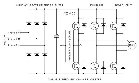
Voltage Source Inverter (VSI)
A Voltage Source Inverter (VSI) is the most common type of VFD circuit. It consists of a rectifier, a DC bus, and an inverter. The rectifier converts the incoming AC power to DC, which is then filtered and smoothed by the DC bus capacitors. The inverter then converts the DC back to AC, with variable frequency and voltage, to control the motor speed and torque.
Here’s a simple schematic of a VSI VFD:
         Rectifier      DC Bus        Inverter
AC Input -->|---|-->|----------|-->|----------|---> AC Output to Motor
            |   |   |          |   |          |
            |   |   |          |   |          |
            |   |   |          |   |          |
            |   |   |          |   |          |
            |---|   |----------|   |----------|
Current Source Inverter (CSI)
A Current Source Inverter (CSI) is less common than a VSI. It uses a controlled rectifier to convert the incoming AC power to a variable DC current, which is then fed to the inverter. The inverter switches the DC current to create an AC output with variable frequency and voltage. CSIs are typically used in high-power applications, such as large industrial motors.
Here’s a simple schematic of a CSI VFD:
         Controlled     Inverter
AC Input -->|---|-->|----------|---> AC Output to Motor
            |   |   |          |
            |   |   |          |
            |   |   |          |
            |   |   |          |
            |---|   |----------|
Pulse Width Modulation (PWM) VFD
Pulse Width Modulation (PWM) is a technique used in modern VFDs to control the output voltage and frequency. In a PWM VFD, the DC bus voltage is switched on and off rapidly by the inverter switches, creating a series of pulses. By varying the width of these pulses (hence the name Pulse Width Modulation), the inverter can control the average voltage and frequency supplied to the motor.
Here’s a simple schematic of a PWM VFD:
         Rectifier      DC Bus        PWM Inverter
AC Input -->|---|-->|----------|-->|----------|---> AC Output to Motor
            |   |   |          |   |          |
            |   |   |          |   |          |
            |   |   |          |   |          |
            |   |   |          |   |          |
            |---|   |----------|   |----------|

How to Build a Basic VFD
Building a basic VFD requires a good understanding of power electronics and control systems. Here’s a step-by-step guide on how to build a simple VSI VFD:
- Gather the necessary components:
- Rectifier (diodes or thyristors)
- DC bus capacitors
- IGBT or MOSFET inverter module
- Control circuit (microcontroller, driver ICs, etc.)
- Voltage and current sensors
- Heat sink and cooling fan
-
Enclosure and mounting hardware
-
Design the power circuit:
- Select the appropriate rectifier based on the input voltage and current requirements.
- Calculate the DC bus capacitance needed to smooth the rectified DC Voltage.
- Choose an inverter module that can handle the required output power and current.
-
Design the DC bus and inverter circuitry, including any necessary protection devices (e.g., fuses, snubbers).
-
Design the control circuit:
- Select a microcontroller or control IC that can generate the necessary PWM signals for the inverter.
- Design the gate driver circuits to interface the control signals with the inverter switches.
-
Implement any necessary feedback and control algorithms (e.g., V/Hz control, sensorless vector control).
-
Assemble the VFD:
- Mount the components on a suitable heat sink and enclosure.
- Wire the power and control circuits according to the schematic.
-
Double-check all connections and ensure proper insulation and clearances.
-
Test and commission the VFD:
- Apply power to the VFD and verify the DC bus voltage.
- Test the control circuit and ensure proper PWM generation.
- Connect a motor to the VFD output and perform basic functional tests (e.g., start, stop, speed control).
- Fine-tune any control parameters and perform full-load tests.
Building a VFD from scratch can be a complex and time-consuming process. It is recommended to start with a simple design and gradually add more features and capabilities as you gain experience. Always follow proper safety precautions and consult with experienced professionals if you are unsure about any aspect of the design or construction process.

FAQ
- What are the advantages of using a VFD?
- Energy savings: VFDs can reduce energy consumption by controlling the motor speed according to the load requirements.
- Improved process control: VFDs allow precise control of motor speed and torque, enhancing process control and product quality.
- Reduced mechanical stress: Soft-starting and stopping capabilities of VFDs reduce mechanical stress on the motor and driven equipment.
-
Extended equipment life: By reducing mechanical stress and controlling the motor within its optimal operating range, VFDs can extend the life of the motor and associated equipment.
-
What are the main components of a VFD?
- Rectifier: Converts incoming AC power to DC.
- DC bus: Filters and smooths the rectified DC voltage.
- Inverter: Converts the DC voltage back to AC with variable frequency and voltage.
-
Control circuit: Generates the necessary control signals for the inverter and monitors the system parameters.
-
What is the difference between a VSI and a CSI VFD?
-
A VSI (Voltage Source Inverter) VFD uses a diode or thyristor rectifier to convert AC to DC and then uses an inverter to convert DC back to AC with variable frequency and voltage. A CSI (Current Source Inverter) VFD, on the other hand, uses a controlled rectifier to convert AC to a variable DC current, which is then fed directly to the inverter.
-
What is PWM, and how does it work in a VFD?
-
PWM (Pulse Width Modulation) is a technique used in VFDs to control the output voltage and frequency. The DC bus voltage is switched on and off rapidly by the inverter switches, creating a series of pulses. By varying the width of these pulses, the inverter can control the average voltage and frequency supplied to the motor.
-
What safety precautions should be taken when working with VFDs?
- Always disconnect power before working on a VFD or the connected motor.
- Ensure proper grounding of the VFD and the motor to prevent electrical shock and equipment damage.
- Use appropriate personal protective equipment (PPE) when working with electrical devices.
- Follow the manufacturer’s instructions and guidelines for installation, operation, and maintenance of the VFD.
- Consult with experienced professionals if you are unsure about any aspect of the VFD installation or operation.

Conclusion
VFD schematics and circuit diagrams are essential tools for understanding the functioning and troubleshooting of Variable Frequency Drives. The three main types of VFD circuits are Voltage Source Inverters (VSI), Current Source Inverters (CSI), and Pulse Width Modulation (PWM) VFDs. Building a basic VFD requires a good understanding of power electronics and control systems, and should be undertaken with proper safety precautions and guidance from experienced professionals. By mastering VFD schematics and circuits, engineers and technicians can design, maintain, and troubleshoot these powerful motor control devices effectively.
No responses yet