Introduction to Thermal PCB Diagnostics
Printed Circuit Boards (PCBs) are the backbone of modern electronic devices, from smartphones and laptops to industrial control systems and medical equipment. As these devices become more complex and compact, the need for efficient and reliable PCB diagnostics becomes increasingly important. Thermal PCB diagnostics is a powerful technique that utilizes thermal imaging cameras to detect and analyze heat patterns on PCBs, enabling engineers and technicians to identify potential issues and optimize board performance.
What is Thermal Imaging?
Thermal imaging, also known as infrared imaging, is a non-contact method of detecting and measuring heat radiation emitted by objects. Thermal cameras capture this infrared radiation and convert it into visible images, where different colors or grayscale levels represent different temperatures. This allows users to visualize heat distribution patterns and identify areas of interest, such as hot spots or cold zones, on a PCB.
Benefits of Thermal PCB Diagnostics
Thermal PCB diagnostics offers several advantages over traditional diagnostic methods:
- Non-contact and non-invasive: Thermal imaging does not require physical contact with the PCB, eliminating the risk of damage or interference with the board’s operation.
- Real-time analysis: Thermal cameras provide instant feedback on heat distribution patterns, enabling users to quickly identify potential issues and make necessary adjustments.
- Comprehensive coverage: Thermal imaging can capture the entire PCB at once, providing a comprehensive overview of the board’s thermal performance.
- Early fault detection: By identifying abnormal heat patterns, thermal PCB diagnostics can help detect potential faults before they lead to component failure or system malfunction.
Thermal Camera Technology
Types of Thermal Cameras
There are two main types of thermal cameras used in PCB diagnostics:
- Uncooled thermal cameras: These cameras use a microbolometer detector that does not require active cooling. They are more affordable and compact but have lower sensitivity and resolution compared to cooled cameras.
- Cooled thermal cameras: These cameras use a photon detector that is cooled to cryogenic temperatures, typically using a Stirling cycle cooler. They offer higher sensitivity, resolution, and frame rates but are more expensive and bulky than uncooled cameras.
Key Specifications of Thermal Cameras
When selecting a thermal camera for PCB diagnostics, consider the following key specifications:
- Resolution: The number of pixels in the thermal detector, which determines the level of detail in the thermal image.
- Thermal sensitivity: The smallest temperature difference the camera can detect, measured in milliKelvins (mK).
- Spectral range: The range of infrared wavelengths the camera can detect, typically between 7 and 14 micrometers for PCB applications.
- Frame rate: The number of images the camera can capture per second, which affects the smoothness of real-time imaging.
- Temperature range: The minimum and maximum temperatures the camera can measure accurately.
Thermal Camera Integration
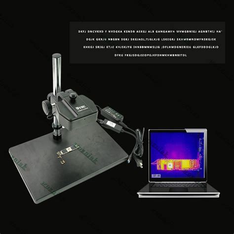
To effectively use thermal cameras for PCB diagnostics, they must be properly integrated into the testing setup. This involves:
- Mounting: The camera should be securely mounted at an appropriate distance and angle relative to the PCB, ensuring a clear and stable view of the board.
- Calibration: Regular calibration is essential to ensure accurate temperature measurements and consistent performance over time.
- Software integration: Thermal imaging software is used to control the camera, capture and analyze thermal data, and generate reports. Ensure compatibility between the camera and software.
Thermal PCB Diagnostic Techniques
Steady-State Thermal Analysis
Steady-state thermal analysis involves capturing thermal images of the PCB under normal operating conditions, when the board has reached thermal equilibrium. This technique helps identify areas of excessive heat generation, uneven heat distribution, and potential hot spots that may lead to component failure or reduced performance.
To perform steady-state thermal analysis:
- Power on the PCB and allow it to reach thermal equilibrium (typically 10-30 minutes, depending on the board’s complexity and power consumption).
- Capture thermal images of the PCB from various angles, ensuring complete coverage of all components and areas of interest.
- Analyze the thermal images using specialized software, comparing the observed heat patterns to expected values and identifying any anomalies.
- If necessary, make adjustments to the PCB design, component selection, or cooling solution to address any identified issues.
Transient Thermal Analysis
Transient thermal analysis involves capturing thermal images of the PCB during dynamic operations, such as power-up, power-down, or changes in load conditions. This technique helps identify thermal transients, power surges, and other time-dependent thermal phenomena that may not be apparent in steady-state analysis.
To perform transient thermal analysis:
- Set up the thermal camera to capture a series of images at a specified frame rate, covering the duration of the dynamic operation.
- Trigger the dynamic operation (e.g., power-up, load change) and simultaneously start the thermal image capture.
- Analyze the series of thermal images using specialized software, looking for any sudden changes in heat patterns, temperature spikes, or other anomalies.
- If necessary, make adjustments to the PCB design, component selection, or power management strategy to address any identified issues.
Comparative Thermal Analysis
Comparative thermal analysis involves comparing thermal images of a PCB to a reference or “golden” sample, which is known to have optimal thermal performance. This technique helps identify deviations from the expected thermal profile, which may indicate manufacturing defects, component variations, or other quality issues.
To perform comparative thermal analysis:
- Capture thermal images of the reference PCB and the PCB under test under identical operating conditions.
- Use specialized software to align and overlay the thermal images, highlighting any differences in heat patterns or temperature values.
- Analyze the differences, considering factors such as component tolerances, manufacturing variations, and environmental conditions.
- If necessary, investigate the root cause of any significant deviations and take appropriate corrective actions, such as component replacement or process improvement.

Interpreting Thermal Images
Color Palettes and Temperature Scales
Thermal cameras typically display temperature data using color palettes, where different colors represent different temperature ranges. Common color palettes include:
- Rainbow: A continuous spectrum from blue (cold) to red (hot), with intermediate colors representing intermediate temperatures.
- Ironbow: Similar to rainbow, but with a more intuitive color progression from black (cold) to white (hot), passing through red and yellow.
- Grayscale: A monochromatic scale from black (cold) to white (hot), with shades of gray representing intermediate temperatures.
When interpreting thermal images, it is essential to pay attention to the temperature scale, which indicates the minimum and maximum temperatures represented in the image. The scale should be adjusted to cover the expected temperature range of the PCB, ensuring optimal contrast and detail in the areas of interest.
Identifying Thermal Anomalies
Thermal anomalies are areas on the PCB that exhibit unexpected or abnormal heat patterns, which may indicate potential issues or defects. Common thermal anomalies include:
- Hot spots: Localized areas of excessive heat generation, which may be caused by component overloading, poor thermal dissipation, or manufacturing defects.
- Cold spots: Areas that appear unexpectedly cool, which may indicate component failure, poor solder connections, or insufficient power delivery.
- Thermal gradients: Abrupt changes in temperature across a small area, which may indicate uneven heat distribution, thermal stress, or poor thermal coupling between components.
When identifying thermal anomalies, consider the following factors:
- Expected thermal profile: Compare the observed heat patterns to the expected thermal profile based on the PCB design, component specifications, and thermal simulation results.
- Component variations: Take into account the natural variations in component temperatures due to differences in power consumption, thermal resistance, and location on the PCB.
- Environmental factors: Consider the impact of ambient temperature, airflow, and other environmental factors on the thermal images, and make appropriate adjustments when comparing results across different conditions.
Correlating Thermal Data with Other Diagnostic Techniques
Thermal PCB diagnostics should be used in conjunction with other diagnostic techniques to provide a comprehensive understanding of the board’s performance and identify the root cause of any issues. Techniques that can be used in combination with thermal imaging include:
- Electrical testing: Measure voltage, current, and resistance at various points on the PCB to verify proper electrical operation and identify any anomalies that may be related to thermal issues.
- Functional testing: Verify that the PCB performs its intended functions correctly, and correlate any performance issues with observed thermal anomalies.
- Visual inspection: Use microscopes or other visual inspection tools to examine the PCB for any physical defects, such as damaged components, poor solder joints, or mechanical stress, that may contribute to thermal issues.
- X-ray inspection: Use X-ray imaging to examine the internal structure of the PCB, including hidden layers, vias, and component connections, which may not be visible in thermal images.
By combining thermal data with information from other diagnostic techniques, engineers and technicians can gain a more comprehensive understanding of the PCB’s performance and make informed decisions about corrective actions and optimizations.
Best Practices for Thermal PCB Diagnostics
To ensure effective and reliable thermal PCB diagnostics, consider the following best practices:
- Proper camera selection: Choose a thermal camera with specifications that match the requirements of your PCB application, considering factors such as resolution, sensitivity, and temperature range.
- Regular calibration: Calibrate the thermal camera regularly to ensure accurate and consistent temperature measurements over time.
- Controlled environment: Perform thermal PCB diagnostics in a controlled environment with stable ambient temperature, minimal air currents, and consistent lighting conditions to minimize external influences on the thermal images.
- Emissivity correction: Apply appropriate emissivity correction factors to the thermal camera settings to account for the different surface properties of PCB components and ensure accurate temperature measurements.
- Consistent setup: Use a consistent testing setup, including camera positioning, PCB orientation, and power supply, to ensure comparable results across different boards and test sessions.
- Adequate thermal stabilization: Allow sufficient time for the PCB to reach thermal equilibrium before capturing steady-state thermal images to ensure representative and consistent results.
- Multiple viewpoints: Capture thermal images from multiple viewpoints and angles to ensure complete coverage of the PCB and minimize the risk of missing critical thermal anomalies.
- Comprehensive analysis: Use specialized thermal analysis software to perform detailed comparisons, trend analysis, and statistical evaluations of the thermal data, going beyond simple visual inspection of the thermal images.
- Collaboration and communication: Foster collaboration and communication between thermal imaging specialists, PCB designers, and other stakeholders to ensure a shared understanding of the thermal diagnostic results and their implications for board performance and reliability.
- Continuous improvement: Regularly review and update thermal PCB diagnostic procedures, incorporating new technologies, best practices, and lessons learned from previous experiences to continuously improve the effectiveness and efficiency of the process.
Case Studies
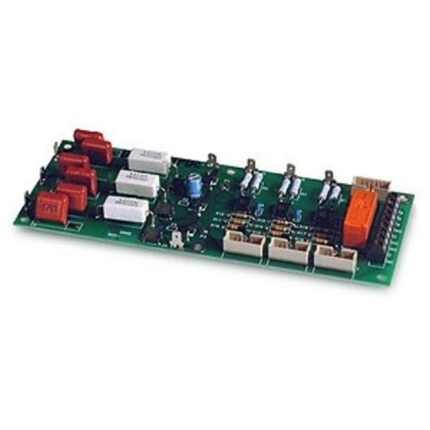
Case Study 1: Identifying a Hot Spot on a Power Supply PCB
A power supply PCB was experiencing intermittent failures during long-term testing. Thermal PCB diagnostics was performed to identify potential thermal issues contributing to the failures.
- Steady-state thermal analysis revealed a localized hot spot near the main power regulation components, with temperatures exceeding the specified safe operating range.
- Visual inspection of the affected area showed signs of discoloration and heat damage on the components and PCB substrate.
- Electrical testing confirmed that the power regulation circuit was not operating within the expected parameters, with voltage fluctuations and increased current draw during the failures.
- The root cause was identified as insufficient thermal dissipation due to inadequate heatsinking and airflow around the power regulation components.
- The PCB design was modified to include a larger heatsink, improved thermal interface materials, and optimized airflow paths, resulting in lower operating temperatures and eliminated the intermittent failures.
Case Study 2: Comparative Thermal Analysis of a Batch of Automotive ECUs
A batch of automotive engine control units (ECUs) was subjected to comparative thermal analysis as part of a quality control process.
- Thermal images of a reference “golden” ECU were captured under standard operating conditions, establishing the expected thermal profile.
- Thermal images of each ECU in the batch were captured under identical conditions and compared to the reference using specialized software.
- Several ECUs exhibited significant deviations from the reference thermal profile, with some components showing elevated temperatures and others showing reduced temperatures.
- Further investigation revealed that the affected ECUs had components from a different supplier, with slightly different thermal characteristics and power consumption.
- The component variations were determined to be within acceptable tolerance ranges, and the ECUs were approved for use, but the findings prompted a review of the supplier qualification and quality control processes to prevent future inconsistencies.
These case studies demonstrate the practical application of thermal PCB diagnostics in identifying and resolving thermal issues, as well as ensuring consistent quality across production batches.
Frequently Asked Questions (FAQ)
-
What is the difference between uncooled and cooled thermal cameras for PCB diagnostics?
Uncooled thermal cameras use a microbolometer detector that does not require active cooling, making them more affordable and compact. Cooled thermal cameras use a photon detector that is cooled to cryogenic temperatures, offering higher sensitivity, resolution, and frame rates, but at a higher cost and larger size. -
How do I choose the right thermal camera for my PCB diagnostic needs?
When selecting a thermal camera for PCB diagnostics, consider factors such as resolution, thermal sensitivity, spectral range, frame rate, and temperature range. Evaluate your specific application requirements, such as the size and complexity of the PCBs, the expected temperature ranges, and the level of detail needed in the thermal images. Consult with thermal imaging experts and review case studies to determine the most suitable camera for your needs. -
What are some common causes of thermal anomalies on PCBs?
Common causes of thermal anomalies on PCBs include component overloading, poor thermal dissipation, manufacturing defects, component failures, poor solder connections, insufficient power delivery, and uneven heat distribution. These issues can manifest as hot spots, cold spots, or thermal gradients in the thermal images, indicating potential problems that require further investigation and corrective action. -
How often should I perform thermal PCB diagnostics?
The frequency of thermal PCB diagnostics depends on factors such as the criticality of the application, the production volume, and the expected reliability requirements. For high-volume production, thermal diagnostics may be performed on a sample basis as part of regular quality control procedures. For critical applications, such as aerospace or medical devices, thermal diagnostics may be performed on every board to ensure the highest level of reliability. In general, thermal diagnostics should be performed whenever there are changes to the PCB design, components, or manufacturing process, or when performance issues or failures are observed. -
Can thermal PCB diagnostics completely replace other diagnostic techniques?
While thermal PCB diagnostics is a powerful and versatile technique, it should not be used as a complete replacement for other diagnostic methods. Thermal imaging provides valuable information about the thermal performance of the PCB, but it does not directly measure electrical, functional, or mechanical aspects. To gain a comprehensive understanding of the PCB’s performance and identify the root cause of any issues, thermal diagnostics should be used in conjunction with other techniques, such as electrical testing, functional testing, visual inspection, and X-ray inspection. By correlating thermal data with information from other diagnostic methods, engineers and technicians can make informed decisions about corrective actions and optimizations.
Conclusion
Thermal PCB diagnostics is a valuable tool for ensuring the reliability, performance, and quality of electronic devices. By leveraging the power of thermal imaging cameras, engineers and technicians can quickly and non-invasively identify potential thermal issues, optimize PCB designs, and prevent failures in the field.
To effectively implement thermal PCB diagnostics, it is essential to select the right thermal camera, establish proper testing procedures, and follow best practices for capturing, analyzing, and interpreting thermal data. By combining thermal diagnostics with other diagnostic techniques and fostering collaboration between thermal imaging specialists and PCB designers, organizations can improve the efficiency and effectiveness of their PCB development and manufacturing processes.
As electronic devices continue to advance in complexity and miniaturization, the importance of thermal PCB diagnostics will only continue to grow. By staying up-to-date with the latest thermal imaging technologies, best practices, and case studies, engineers and technicians can ensure that their PCBs are designed, manufactured, and deployed with the highest levels of reliability and performance.
No responses yet