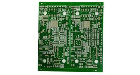
Introduction to PCB Fabrication and Draftsman
Printed Circuit Board (PCB) fabrication is a crucial process in the electronics industry, enabling the creation of complex electronic circuits on a compact, durable substrate. To ensure that PCBs are manufactured accurately and efficiently, engineers and designers rely on specialized software tools to create detailed fabrication drawings. One such tool is Draftsman, a powerful PCB documentation solution that simplifies the creation of high-quality fabrication drawings.
In this article, we will explore the process of using Draftsman to create PCB fabrication drawings, covering the key features, benefits, and best practices for optimizing your design workflow.
Understanding the Importance of PCB Fabrication Drawings
The Role of Fabrication Drawings in PCB Manufacturing
PCB fabrication drawings, also known as manufacturing drawings or production drawings, are essential documents that provide a clear, comprehensive visual representation of a PCB design. These drawings contain all the necessary information required by PCB manufacturers to accurately produce the board, including:
- Board dimensions and shape
- Layer stackup and materials
- Copper traces and pads
- Drill holes and vias
- Silkscreen and solder mask
- Assembly notes and special instructions
By providing a complete and unambiguous set of instructions, fabrication drawings ensure that the manufactured PCB meets the designer’s specifications and functions as intended.
The Benefits of Using Draftsman for PCB Fabrication Drawings
Draftsman is a powerful, purpose-built tool for creating PCB fabrication drawings, offering numerous benefits over traditional, manual drawing methods or generic CAD software:
- Automation: Draftsman automatically generates drawings from your PCB design files, saving time and reducing the risk of errors.
- Customization: With Draftsman, you can easily customize your drawings to meet specific manufacturer requirements or design standards.
- Consistency: Draftsman ensures consistent, professional-quality output across all your fabrication drawings.
- Integration: As part of the Altium Designer ecosystem, Draftsman seamlessly integrates with your PCB design workflow, enabling real-time updates and synchronization.
By leveraging the capabilities of Draftsman, you can streamline your PCB documentation process, improve communication with manufacturers, and ultimately, achieve better results in your PCB fabrication projects.

Getting Started with Draftsman
System Requirements and Installation
To use Draftsman for creating PCB fabrication drawings, you will need a computer running Microsoft Windows with the following minimum system requirements:
- Operating System: Microsoft Windows 10 (64-bit)
- Processor: 64-bit, 2 GHz or faster
- RAM: 8 GB or more
- Storage: 5 GB of free disk space
- Display: 1920 x 1080 resolution or higher
Draftsman is included as part of the Altium Designer installation package. To install Altium Designer and Draftsman:
- Download the latest version of Altium Designer from the official Altium website (https://www.altium.com/products/downloads).
- Run the installer and follow the on-screen instructions to complete the installation process.
- Launch Altium Designer, and you will find Draftsman accessible from within the software.
Configuring Draftsman Settings and Preferences
Before creating your first fabrication drawing with Draftsman, it’s essential to configure the software settings and preferences to suit your specific requirements. To access the Draftsman settings:
- Open Altium Designer and navigate to the “DXP” menu.
- Click “Preferences” to open the Preferences dialog.
- In the left pane, expand the “Draftsman” folder to reveal the available settings categories.
Some key settings to consider include:
- Drawing Formats: Set the default drawing sheet size, border, and title block.
- Dimension Settings: Customize the appearance and behavior of dimensions in your drawings.
- Layer Settings: Configure the visibility and properties of layers in your fabrication drawings.
- Annotation Settings: Adjust the style and placement of annotations, such as notes and callouts.
Take the time to review and customize these settings to ensure that your fabrication drawings meet your company’s standards and the requirements of your PCB manufacturers.

Creating PCB Fabrication Drawings with Draftsman
Importing PCB Design Data
To create a fabrication drawing with Draftsman, you first need to import your PCB design data from Altium Designer. Draftsman supports various design file formats, including:
- Altium Designer PCB files (.PcbDoc)
- ODB++ files (.tgz, .tar, .zip)
- Gerber files (.gbr, .gm1, .gko, .gm1, .gbs, .gbo, .gts, .gto, .gtp)
To import your PCB design data:
- In Altium Designer, open your PCB project.
- Select “File” > “Fabrication Outputs” > “Draftsman” to open Draftsman.
- In the Draftsman workspace, click “File” > “New” > “Drawing” to create a new drawing document.
- In the “Select Data Source” dialog, choose your PCB file or fabrication output files, and click “OK.”
Draftsman will import your PCB design data and display it in the drawing workspace, ready for you to begin creating your fabrication drawing.
Adding Views and Details
With your PCB design data imported, you can start adding views and details to your fabrication drawing. Draftsman provides a range of drawing views and detail types to help you effectively communicate your design intent:
- Assembly View: Shows the component placement and orientation on the PCB.
- Fabrication View: Displays the copper layers, drill holes, and other manufacturing features.
- Layer Stack View: Illustrates the arrangement and materials of the PCB layers.
- Drill Table: Lists the drill sizes, quantities, and symbols used in the design.
- Bill of Materials (BOM): Provides a tabular list of components used in the PCB assembly.
To add a view or detail to your drawing:
- In the Draftsman workspace, click the “Add View” or “Add Detail” button in the ribbon.
- Select the desired view or detail type from the dropdown menu.
- Configure the view or detail settings in the Properties panel.
- Place the view or detail on your drawing sheet by clicking and dragging in the workspace.
Repeat this process to add additional views and details as needed to fully document your PCB design.
Dimensioning and Annotating
To ensure that your fabrication drawing provides clear and accurate information, it’s crucial to add dimensions and annotations:
-
Dimensions: Use dimensions to specify critical measurements, such as board size, hole locations, and component spacing. To add a dimension, select the “Dimension” tool from the ribbon, choose the dimension type (linear, radial, angular, or Leader), and click on the relevant points in your drawing.
-
Annotations: Add annotations, such as notes, callouts, and symbols, to provide additional information or clarify specific aspects of your design. To add an annotation, select the “Annotation” tool from the ribbon, choose the annotation type, and click in your drawing to place the annotation.
Draftsman provides a variety of options for customizing the appearance and behavior of dimensions and annotations, allowing you to create drawings that adhere to your company’s standards and industry best practices.

Advanced Draftsman Techniques
Using Templates and Styles
To maintain consistency and efficiency in your PCB fabrication drawings, Draftsman allows you to create and use templates and styles:
-
Templates: Drawing templates define the overall layout, sheet size, border, and title block of your fabrication drawings. By creating and using templates, you can ensure that all your drawings have a consistent appearance and include the necessary information. To create a template, set up a drawing with your desired layout and settings, then save it as a template file (.DwgTemplate) for future use.
-
Styles: Draftsman styles allow you to define and apply consistent formatting to drawing elements, such as text, dimensions, and annotations. By creating and applying styles, you can quickly and easily format your drawings to meet specific standards or requirements. To create a style, use the Style Manager in the Draftsman workspace to define the desired properties, then apply the style to the relevant drawing elements.
Leveraging templates and styles in Draftsman can significantly streamline your drawing creation process and help maintain a professional, consistent appearance across all your PCB fabrication documentation.
Automated Drawing Generation and Updating
One of the most powerful features of Draftsman is its ability to automate the generation and updating of fabrication drawings based on changes to your PCB design:
-
Automated Generation: Draftsman can automatically create a complete set of fabrication drawings from your PCB design data, including assembly views, fabrication views, drill tables, and BOMs. To generate drawings automatically, click “File” > “New” > “Automatic Drawing” in the Draftsman workspace, select your PCB file, and choose the desired drawing templates and settings.
-
Automated Updating: When you make changes to your PCB design in Altium Designer, Draftsman can automatically update your fabrication drawings to reflect those changes. To enable automatic updates, click “File” > “Update” > “Perform Update” in the Draftsman workspace, or set up automatic update settings in the Preferences dialog.
By leveraging Draftsman’s automation capabilities, you can save significant time and effort in creating and maintaining your PCB fabrication drawings, while also ensuring that your documentation stays in sync with your evolving design.
Best Practices for PCB Fabrication Drawings
Communication with PCB Manufacturers
Effective communication with your PCB manufacturer is essential for ensuring successful fabrication of your designs. When creating fabrication drawings with Draftsman, consider the following best practices:
- Consult with your manufacturer early in the design process to understand their specific requirements and preferences for fabrication drawings.
- Provide clear, concise, and complete information in your drawings, including all necessary views, details, dimensions, and annotations.
- Use industry-standard file formats, such as Gerber or ODB++, when exporting your fabrication data.
- Include a README file or cover sheet with your fabrication package, outlining any special instructions, requirements, or considerations for your design.
By fostering open, proactive communication with your PCB manufacturer and providing comprehensive, well-organized fabrication drawings, you can minimize the risk of errors, delays, or misunderstandings in the production process.
Quality Control and Design Review
To ensure the accuracy and completeness of your PCB fabrication drawings, it’s crucial to implement quality control measures and conduct thorough design reviews:
-
Use Draftsman’s built-in design rule checks (DRCs) to automatically verify your drawings against a set of predefined rules, such as minimum clearances, hole sizes, or text heights. To run a DRC, click “Tools” > “Design Rule Check” in the Draftsman workspace, select the desired rules, and click “Run Check.”
-
Conduct peer reviews or design walkthroughs with colleagues or subject matter experts to gather feedback, identify potential issues, and ensure that your fabrication drawings meet all relevant standards and requirements.
-
Maintain a checklist of critical items to review in your fabrication drawings, such as board dimensions, layer stackup, drill sizes, and special instructions, to ensure that no essential information is overlooked.
By incorporating rigorous quality control and design review processes into your PCB fabrication drawing workflow, you can catch and correct errors early, reduce the risk of costly rework, and ultimately, achieve better results in your PCB manufacturing projects.
Frequently Asked Questions (FAQ)
-
Can I use Draftsman without Altium Designer?
No, Draftsman is a part of the Altium Designer ecosystem and requires an active Altium Designer license to function. -
What file formats can I export my fabrication drawings to from Draftsman?
Draftsman supports exporting fabrication drawings to a variety of file formats, including PDF, DWG, DXF, and SVG. -
Can I create custom drawing templates in Draftsman?
Yes, Draftsman allows you to create and save custom drawing templates with your preferred sheet size, border, title block, and other settings. -
How can I ensure that my fabrication drawings meet my manufacturer’s requirements?
Consult with your PCB manufacturer early in the design process to understand their specific requirements for fabrication drawings, and use Draftsman’s customization options to ensure that your drawings adhere to those requirements. -
Can I automate the generation of my fabrication drawings with Draftsman?
Yes, Draftsman offers powerful automation features, allowing you to automatically generate complete sets of fabrication drawings from your PCB design data and update those drawings whenever your design changes.
Conclusion
Creating accurate, comprehensive, and professional-quality PCB fabrication drawings is essential for ensuring the successful manufacture of your electronic designs. By using Draftsman, a powerful, purpose-built tool for PCB documentation, you can streamline your drawing creation process, improve communication with manufacturers, and ultimately, achieve better results in your PCB fabrication projects.
In this article, we explored the key features and benefits of using Draftsman for PCB fabrication drawings, as well as best practices for optimizing your design workflow, communicating with manufacturers, and ensuring the quality and accuracy of your documentation. By following these guidelines and leveraging the full capabilities of Draftsman, you can create fabrication drawings that effectively communicate your design intent and facilitate the smooth, efficient production of your PCBs.
| Drawing Type | Purpose | Key Elements |
|---|---|---|
| Assembly View | Shows component placement and orientation | – Component outlines – Reference designators – Polarity markers |
| Fabrication View | Displays copper layers, drill holes, and manufacturing features | – Copper traces and pads – Drill holes and vias – Board outline and dimensions |
| Layer Stack View | Illustrates the arrangement and materials of PCB layers | – Layer names and thicknesses – Material specifications – Copper weights and finishes |
| Drill Table | Lists drill sizes, quantities, and symbols used in the design | – Drill sizes and tolerances – Hole quantities and types – Plated and non-plated holes |
| Bill of Materials (BOM) | Provides a tabular list of components used in the PCB assembly | – Component reference designators – Part numbers and descriptions – Quantities and values |
By incorporating these essential views and details into your fabrication drawings, you can provide a complete, unambiguous set of instructions for your PCB manufacturer, enabling them to accurately and efficiently produce your designs.

No responses yet