Introduction to USB Charger Design in Altium
Designing a USB charger requires careful planning and execution to ensure the final product is safe, reliable, and meets the necessary specifications. In this article, we will walk through the process of designing a USB charger using Altium Designer, a powerful PCB design software. We will cover everything from selecting components to laying out the PCB and generating manufacturing files. By the end of this guide, you should have a solid understanding of how to design your own USB charger using Altium.
Why Use Altium for USB Charger Design?
Altium Designer is a comprehensive PCB design software that offers a range of features and tools specifically tailored for electronic design. Some key benefits of using Altium for USB charger design include:
- Integrated schematic capture and PCB layout environment
- Extensive component libraries
- Powerful routing and placement tools
- 3D visualization and clearance checking
- Automated manufacturing file generation
With Altium, you can streamline your design process and ensure your USB charger meets all necessary requirements. Let’s dive into the specifics of USB charger design.
USB Charger Design Specifications and Requirements
Before starting your USB charger design, it’s important to define the key specifications and requirements. This will guide your component selection and design decisions. Some important specs to consider include:
USB Charging Standards
There are several USB charging standards that dictate the allowable voltage and current levels:
| Standard | Voltage | Max Current |
|---|---|---|
| USB 2.0 | 5V | 500mA |
| USB 3.0 | 5V | 900mA |
| USB BC 1.2 | 5V | 1.5A |
| USB PD | 5-20V | 5A |
Choose the standard that aligns with your desired charger capabilities. USB PD allows for the highest power output.
Input Power Source
Consider what will be powering your USB charger. Common options are:
- AC mains (wall outlet)
- 12V car adapter
- Other DC source
The input power spec will determine what power conversion circuitry is needed.
Number of Ports
Decide how many USB ports your charger will have. More ports increase design complexity but allow charging multiple devices. Typical options are:
- 1 port
- 2 ports
- 4 ports
Safety and Compliance
USB chargers must meet strict safety and regulatory standards:
- UL/IEC 60950-1 for IT equipment
- CE marking for sale in Europe
- FCC Part 15 for electromagnetic compliance
Be sure to design with these requirements in mind. Now that we’ve outlined the key specifications, let’s look at selecting components.
Choosing Components for a USB Charger
With your USB charger requirements defined, you can start selecting components. There are several key parts needed:
USB Receptacle
The USB receptacle is where devices plug into the charger. Choose a receptacle that matches your selected USB standard. Some options:
| Part Number | Description | Supplier |
|---|---|---|
| 896-USB1046-GF-A | USB-A receptacle, USB 3.0, vertical | Mouser |
| 2073-USB4085-GF-ACT | USB-C receptacle, USB 3.1, vertical | Mouser |
Voltage Regulator
A voltage regulator converts the input voltage to the desired USB voltage level (typically 5V). Options include:
- Linear regulators (e.g. LM7805)
- Switching regulators (e.g. TPS62150)
Switching regulators are more efficient but also more complex. For a 5V USB charger, a linear regulator is often sufficient.
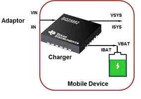
Protection IC
A protection IC safeguards the connected device from overvoltage, undervoltage, and overcurrent conditions. The TI TPS2546 or On Semi NCP380 are good options.
Passive Components
Various resistors, capacitors, and inductors are needed for the power circuitry, indicator LEDs, etc. Consult the datasheets of your selected ICs for recommended values.

Designing the USB Charger in Altium
With components selected, we can start designing our USB charger in Altium. The general process is:
- Create a new Altium project
- Create a schematic of the charger circuitry
- Layout the PCB based on the schematic
- Generate manufacturing files
Let’s go through each step in more detail. Altium provides an integrated environment for all stages.
Creating the USB Charger Schematic
The schematic defines the connectivity between components. To create the schematic:
- Make a new schematic in your Altium project
- Place your selected components from Altium’s libraries
- Wire together the components, consulting datasheets for reference designs
- Add net labels, power symbols, etc. for completeness
- Perform a design rule check (DRC) for errors
Take your time to ensure the schematic is correct. A good schematic makes PCB layout much easier.
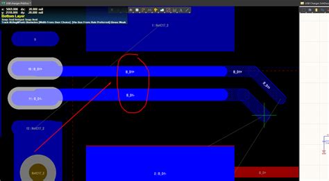
Laying Out the USB Charger PCB
With a completed schematic, you can move on to PCB layout. The key steps are:
- Define the board shape and size
- Place components, prioritizing placement of the USB receptacle, voltage regulator, and protection IC
- Route traces, focusing on power paths first
- Create a ground plane for low impedance grounding
- Add any needed mounting holes, silkscreen, etc.
- Perform a design rule check for any errors
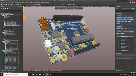
Optimize your placement and routing for manufacturability. Consult Altium’s 3D view to check for clearance issues.
Generating Manufacturing Files
After you’ve finalized your PCB layout, you’ll need to generate manufacturing files to have your board produced. Key files include:
- Gerber files (copper layers, soldermask, silkscreen)
- NC drill files (hole sizes and locations)
- Pick and place file (component placement data)
- BOM (bill of materials)
Altium can automatically generate these files. Be sure to double-check them before sending off to your manufacturer.
Testing and Troubleshooting
With PCBs in hand, it’s time to test your USB charger. Recommended tests include:
- Continuity testing (ensure no short circuits)
- Input voltage testing
- Output voltage testing (should match selected USB standard)
- Load testing (plug in a device and verify successful charging)
If you encounter any issues, methodically troubleshoot your charger. Check voltages at key test points, like regulator input/output. Inspect solder joints for good connections.
Document your testing process and results. This information will be valuable for future designs and any certification processes.
FAQ
What if my USB charger isn’t providing enough current?
There could be a few causes:
– Ensure your input power supply is providing enough current
– Check that your selected voltage regulator is rated for the desired current output
– Look for any above-normal voltage drops that could indicate issues
Can I design a USB charger with both USB-A and USB-C ports?
Yes, you can mix and match receptacle types. Just be sure to select compatible voltage regulators and protection ICs, and lay out the board accordingly.
What if my charger is getting too hot?
USB chargers can generate heat, especially at high currents. Some things to check:
– Make sure components are sized appropriately and not being overloaded
– Check for good thermal contact between hot components and the PCB
– Consider adding thermal reliefs or heat sinks if needed
How do I get my USB charger certified?
Certification requirements vary by country and market. Some general steps:
1. Determine what certifications are needed (UL, FCC, CE, etc.)
2. Perform in-house testing to applicable standards
3. Send samples to an accredited lab for formal testing
4. Submit paperwork for certification marks
The certification process can be lengthy, so plan accordingly.
Conclusion
Designing a USB charger may seem daunting, but Altium Designer provides the tools to make the process manageable. By carefully defining specifications, selecting quality components, and optimizing your schematic and PCB layout, you can create a USB charger that’s reliable, efficient, and safe.
Remember to thoroughly test your charger and seek any necessary certifications before putting it into production. With proper planning and execution, your USB charger design can be a success.
For more information on USB charger design and Altium, consult the following resources:
– Altium documentation and training materials
– USB-IF specifications and whitepapers
– Industry guides on power supply design
Happy designing!
No responses yet