Introduction to USB4 and Its Benefits for PCB Design
USB4 is the latest iteration of the Universal Serial Bus (USB) standard, offering unprecedented speed and efficiency for data transfer in electronic devices. As a PCB designer, understanding the key features and benefits of USB4 is crucial to creating high-performance products that meet the demands of today’s market.
USB4 builds upon the success of USB 3.2 and incorporates the Thunderbolt 3 protocol, enabling faster data transfer speeds, improved power delivery, and enhanced display capabilities. By implementing USB4 in your PCB design, you can deliver cutting-edge products that offer superior performance and functionality.
Key Features of USB4
- High-speed data transfer: USB4 supports data transfer rates of up to 40 Gbps, twice the speed of USB 3.2 Gen 2×2.
- Thunderbolt 3 compatibility: USB4 integrates Thunderbolt 3 technology, allowing for seamless compatibility with Thunderbolt 3 devices.
- Improved power delivery: USB4 supports power delivery of up to 100W, enabling faster charging and the ability to power more demanding devices.
- Versatile display capabilities: USB4 can drive multiple high-resolution displays, including 8K displays and high-refresh-rate monitors.
USB4 Architecture and Its Impact on PCB Design
To effectively implement USB4 in your PCB design, it is essential to understand its architecture and how it differs from previous USB standards. USB4 utilizes a new protocol layer, which enables more efficient data encoding and decoding, resulting in faster data transfer speeds and lower latency.
USB4 Protocol Layer
The USB4 protocol layer introduces two key features that contribute to its enhanced performance:
- 128b/132b encoding: USB4 uses a more efficient encoding scheme compared to the 8b/10b encoding used in previous USB standards. This allows for higher data throughput and reduced overhead.
- Link training and status state machine (LTSSM): The LTSSM manages the link between the host and the device, ensuring optimal performance and reliability.
USB4 Physical Layer
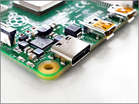
The physical layer of USB4 is based on the USB Type-C connector and cable, which offers several advantages over previous USB connectors:
- Reversibility: The USB Type-C connector can be inserted either way up, making it more user-friendly and reducing the risk of damage.
- Higher power delivery: USB Type-C cables can deliver up to 100W of power, enabling faster charging and the ability to power more demanding devices.
- Alternate Mode support: USB Type-C ports can support various Alternate Modes, such as DisplayPort and Thunderbolt, allowing for greater versatility in PCB design.
Designing PCBs for USB4 Compliance
To ensure your PCB design is USB4 compliant, there are several key considerations you must take into account. These include signal integrity, power delivery, and electromagnetic compatibility (EMC).
Signal Integrity Considerations
USB4’s high data transfer speeds require careful attention to signal integrity to maintain optimal performance. Some key signal integrity considerations include:
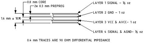
- Impedance matching: Ensuring proper impedance matching between the USB4 controller, connectors, and traces is crucial to minimize reflections and signal distortion.
- Length matching: USB4 differential pairs must be length-matched to maintain signal integrity and minimize skew.
- Crosstalk reduction: Adequate spacing and shielding between USB4 traces and other high-speed signals help reduce crosstalk and maintain signal quality.
Power Delivery Considerations
USB4’s enhanced power delivery capabilities require careful design of the power delivery network on your PCB. Key considerations include:
- Power supply design: Ensuring the USB4 power supply is capable of delivering the required current and voltage levels without excessive ripple or noise.
- Decoupling capacitors: Proper placement and selection of decoupling capacitors help maintain power integrity and reduce noise on the power supply rails.
- Thermal management: Adequate cooling and thermal management are essential to prevent overheating of the USB4 controller and other power delivery components.
EMC Considerations
USB4’s high-speed signals can generate significant electromagnetic interference (EMI), which must be mitigated to ensure compliance with EMC regulations. Key EMC considerations include:
- Shielding: Implementing proper shielding techniques, such as ground planes and shielded connectors, can help reduce EMI emissions.
- Filtering: Using appropriate filtering techniques, such as ferrite beads and common-mode chokes, can help suppress high-frequency noise and reduce EMI.
- Layout techniques: Proper layout techniques, such as minimizing loop areas and avoiding unnecessary stubs, can help reduce EMI and improve overall EMC performance.

Implementing USB4 in Your PCB Design Workflow
Integrating USB4 into your PCB design workflow requires careful planning and execution. Here are some key steps to follow:
- Select the appropriate USB4 controller: Choose a USB4 controller that meets your design requirements, such as data transfer speed, power delivery, and display capabilities.
- Design the USB4 circuit: Create the USB4 circuit schematic, including the controller, connectors, and necessary support components, such as power supplies and decoupling capacitors.
- Perform signal integrity simulations: Use signal integrity simulation tools to analyze the USB4 signals and ensure they meet the required specifications for impedance, length matching, and crosstalk.
- Design the PCB layout: Create the PCB layout, focusing on the placement and routing of the USB4 components and traces. Ensure proper impedance matching, length matching, and spacing to maintain signal integrity and minimize EMI.
- Perform power integrity simulations: Use power integrity simulation tools to analyze the USB4 power delivery network and ensure it meets the required specifications for voltage, current, and ripple.
- Perform EMC simulations: Use EMC simulation tools to analyze the EMI emissions from the USB4 circuit and ensure compliance with relevant EMC regulations.
- Prototype and test: Manufacture a prototype of your USB4 PCB and perform thorough testing to validate its performance and compliance with USB4 specifications.
Future Trends and Developments in USB4 Technology
As USB4 continues to gain adoption in the electronics industry, we can expect to see further developments and improvements in the technology. Some potential future trends include:
- Higher data transfer speeds: As demand for faster data transfer grows, we may see future versions of USB4 supporting even higher speeds, such as 80 Gbps or beyond.
- Improved power delivery: Future USB4 specifications may support even higher power delivery capabilities, enabling faster charging and the ability to power more demanding devices.
- Greater integration with other technologies: USB4 may see greater integration with other high-speed communication technologies, such as PCIe and Ethernet, enabling more versatile and efficient PCB designs.
- Increased adoption in various industries: USB4 is likely to see increased adoption in various industries beyond consumer electronics, such as automotive, industrial, and medical applications, driving further innovation and development of the technology.
Frequently Asked Questions (FAQ)
-
What is the maximum data transfer speed supported by USB4?
USB4 supports data transfer speeds of up to 40 Gbps, which is twice the speed of USB 3.2 Gen 2×2. -
Is USB4 compatible with Thunderbolt 3 devices?
Yes, USB4 integrates Thunderbolt 3 technology, allowing for seamless compatibility with Thunderbolt 3 devices. -
What is the maximum power delivery capability of USB4?
USB4 supports power delivery of up to 100W, enabling faster charging and the ability to power more demanding devices. -
What are some key signal integrity considerations when designing PCBs for USB4?
Key signal integrity considerations for USB4 PCB design include impedance matching, length matching, and crosstalk reduction between USB4 traces and other high-speed signals. -
How can I ensure my USB4 PCB design is compliant with EMC regulations?
To ensure EMC compliance, implement proper shielding techniques, use appropriate filtering components, and follow best practices for PCB layout to minimize EMI emissions. Conducting EMC simulations and thorough testing can help validate compliance.
Conclusion
USB4 represents a significant advancement in high-speed serial data transfer technology, offering unprecedented speed, efficiency, and versatility for PCB designers. By understanding the key features and benefits of USB4, as well as the design considerations for signal integrity, power delivery, and EMC, you can create cutting-edge products that meet the demands of today’s market.
As USB4 continues to evolve and gain adoption across various industries, staying up-to-date with the latest developments and best practices in USB4 PCB design will be crucial to remaining competitive and delivering innovative, high-performance products to your customers.
No responses yet