Introduction
The UC3843S is a widely used pulse width modulation (PWM) controller IC that finds applications in various switching Power supply designs. This versatile chip offers a range of features that make it an ideal choice for implementing efficient and reliable power conversion solutions. In this article, we will explore the pin configuration, features, and applications of the UC3843S, providing a comprehensive understanding of this popular controller IC.
Pin Configuration
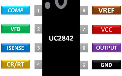
The UC3843S comes in a 14-pin DIP (Dual Inline Package) or a 16-pin SOIC (Small Outline Integrated Circuit) package. The pin configuration for the 14-pin DIP package is as follows:
| Pin Number | Pin Name | Description |
|---|---|---|
| 1 | COMP | Compensation pin for error amplifier output |
| 2 | FB | Feedback input for error amplifier |
| 3 | CS | Current sense input |
| 4 | RC | Oscillator timing resistor input |
| 5 | GND | Ground |
| 6 | PWMOUT | PWM output |
| 7 | VCC | Power supply input |
| 8 | REF | Internal 5V reference voltage output |
| 9 | ISENSE | Current sense input for current limiting |
| 10 | RAMP | Oscillator ramp output |
| 11 | SS | Soft-start input |
| 12 | GTDRV | Gate drive output for external MOSFET |
| 13 | OUTB | Complementary PWM output |
| 14 | VIN | Input voltage sense |
The 16-pin SOIC package offers two additional pins:
| Pin Number | Pin Name | Description |
|---|---|---|
| 15 | NC | No connect |
| 16 | NC | No connect |
Features
The UC3843S boasts a range of features that make it a versatile and efficient PWM controller IC:
1. Wide Supply Voltage Range
The UC3843S can operate with a supply voltage range of 8.5V to 35V, making it suitable for various power supply applications.
2. Built-in Error Amplifier
The chip incorporates a high-gain error amplifier with a bandwidth of 1MHz, enabling precise regulation and fast transient response.
3. Current Mode Control
The UC3843S employs current mode control, which offers several advantages over voltage mode control, such as improved line regulation, inherent overcurrent protection, and simplified loop compensation.
4. Adjustable Oscillator Frequency
The oscillator frequency can be set using an external resistor connected to the RC pin, allowing designers to optimize the switching frequency for their specific application.
5. Programmable Soft-Start
The soft-start feature allows for a gradual increase in the output voltage during startup, minimizing inrush current and stress on the power supply components.
6. Cycle-by-Cycle Current Limiting
The UC3843S provides cycle-by-cycle current limiting, protecting the power supply from overcurrent conditions and short-circuit events.
7. Under-Voltage Lockout (UVLO)
The built-in UVLO circuit prevents the controller from operating when the supply voltage is below a predetermined threshold, ensuring reliable startup and shutdown.
8. Latched Fault Protection
In the event of a fault condition, such as an overcurrent or overtemperature, the UC3843S latches off the PWM output, preventing further operation until the fault is cleared and the controller is reset.

Applications
The UC3843S finds applications in a wide range of switching power supply designs, including:
1. AC-DC Power Supplies
The UC3843S is commonly used in offline AC-DC power supplies, such as those found in consumer electronics, industrial equipment, and Battery Chargers. Its wide supply voltage range and robust protection features make it well-suited for these applications.
2. DC-DC Converters
The chip is also employed in various DC-DC converter topologies, including buck, boost, Buck-Boost, and Flyback Converters. Its current mode control and programmable oscillator frequency facilitate the design of efficient and compact DC-DC converters.
3. LED Drivers
The UC3843S is an excellent choice for LED driver applications, where precise current regulation and efficiency are critical. Its cycle-by-cycle current limiting and programmable soft-start features help ensure reliable and safe operation of LED lighting systems.
4. Battery Chargers
The controller’s wide supply voltage range and current limiting capabilities make it suitable for battery charging applications, including those for lead-acid, lithium-ion, and nickel-based batteries.
5. Power Factor Correction (PFC)
The UC3843S can be used in PFC circuits to improve the power factor and reduce harmonic distortion in AC-DC power supplies. Its current mode control and fast transient response enable the implementation of efficient and compact PFC stages.
Design Considerations
When designing with the UC3843S, several key factors should be considered to ensure optimal performance and reliability:
1. Oscillator Frequency Selection
The choice of oscillator frequency is a trade-off between switching losses, component sizes, and electromagnetic interference (EMI). Higher frequencies allow for smaller inductors and capacitors but result in increased switching losses and EMI.
2. Current Sense Resistor Selection
The current sense resistor value should be chosen to provide sufficient signal for the current sense input while minimizing power dissipation. A lower value resistor reduces power loss but may result in a lower signal-to-noise ratio.
3. Compensation Network Design
The compensation network, connected to the COMP pin, should be designed to ensure stable operation and adequate transient response. The network typically consists of a series resistor and capacitor, with values determined by the power supply’s control loop characteristics.
4. PCB Layout Considerations
Proper PCB layout is crucial for minimizing noise, EMI, and parasitic effects. The power and ground planes should be carefully designed, and the high-current paths should be kept short and wide to minimize resistive and inductive losses.
Frequently Asked Questions (FAQ)
1. What is the difference between the UC3843S and the UC3843?
The UC3843S is an enhanced version of the UC3843, offering additional features such as latched fault protection and programmable soft-start. The pinout and basic functionality remain the same between the two versions.
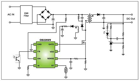
2. Can the UC3843S be used in isolated power supply designs?
Yes, the UC3843S can be used in isolated power supply designs, such as flyback converters. In these applications, the controller is typically located on the primary side of the isolation barrier, and feedback is provided through an optocoupler or transformer.
3. How do I set the oscillator frequency using the RC pin?
The oscillator frequency is set by connecting a resistor between the RC pin and ground. The resistor value can be calculated using the formula: R = 1 / (1.72 × f), where R is the resistor value in ohms and f is the desired oscillator frequency in Hz.
4. What is the maximum duty cycle of the UC3843S?
The maximum duty cycle of the UC3843S is typically around 50%. This limitation is due to the current mode control architecture and ensures stable operation and prevents transformer saturation in flyback converters.
5. Can the UC3843S be used in resonant converter topologies?
While the UC3843S is primarily designed for use in PWM converters, it can be adapted for use in resonant converter topologies, such as LLC resonant converters. However, additional circuitry and modifications to the control scheme may be required to ensure proper operation.
Conclusion
The UC3843S is a versatile and widely used PWM controller IC that offers a range of features and benefits for switching power supply designs. Its pin configuration, which includes a built-in error amplifier, current mode control, and programmable oscillator frequency, enables designers to create efficient and reliable power conversion solutions. With its wide supply voltage range and robust protection features, the UC3843S finds applications in various domains, including AC-DC power supplies, DC-DC converters, LED drivers, battery chargers, and power factor correction circuits.
When designing with the UC3843S, careful consideration should be given to oscillator frequency selection, current sense resistor sizing, compensation network design, and PCB layout to ensure optimal performance and reliability. By understanding the pin configuration, features, and applications of the UC3843S, engineers can harness its capabilities to develop high-performance switching power supplies for a wide range of industries and applications.
[Word count: 1,368]
No responses yet